
Method of making retroreflective sheeting and articles

Active Publication Date: 2005-04-26
3M INNOVATIVE PROPERTIES CO
View PDF29 Cites 70 Cited by
  • Summary
  • Abstract
  • Description
  • Claims
  • Application Information

AI Technical Summary

Benefits of technology

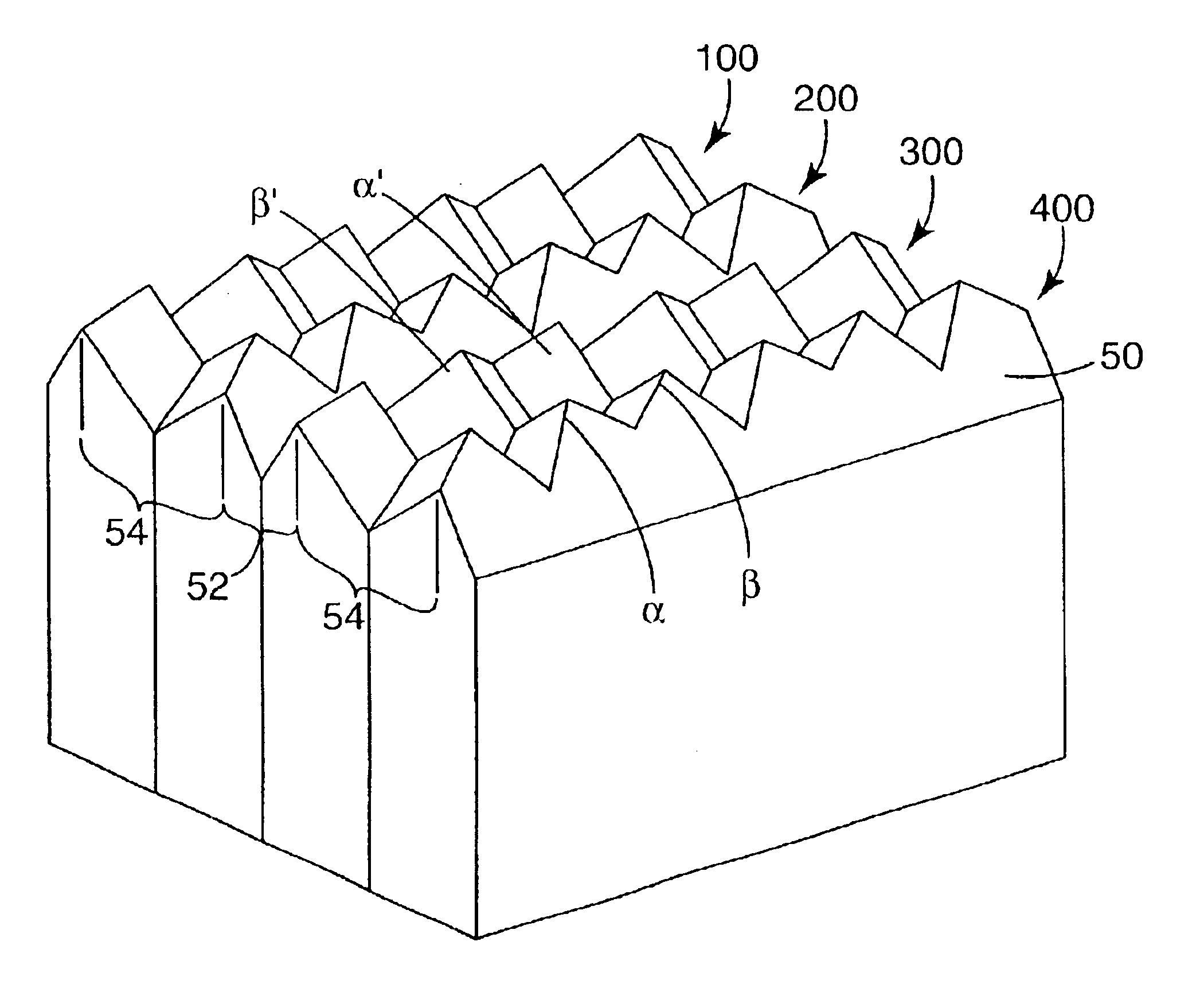
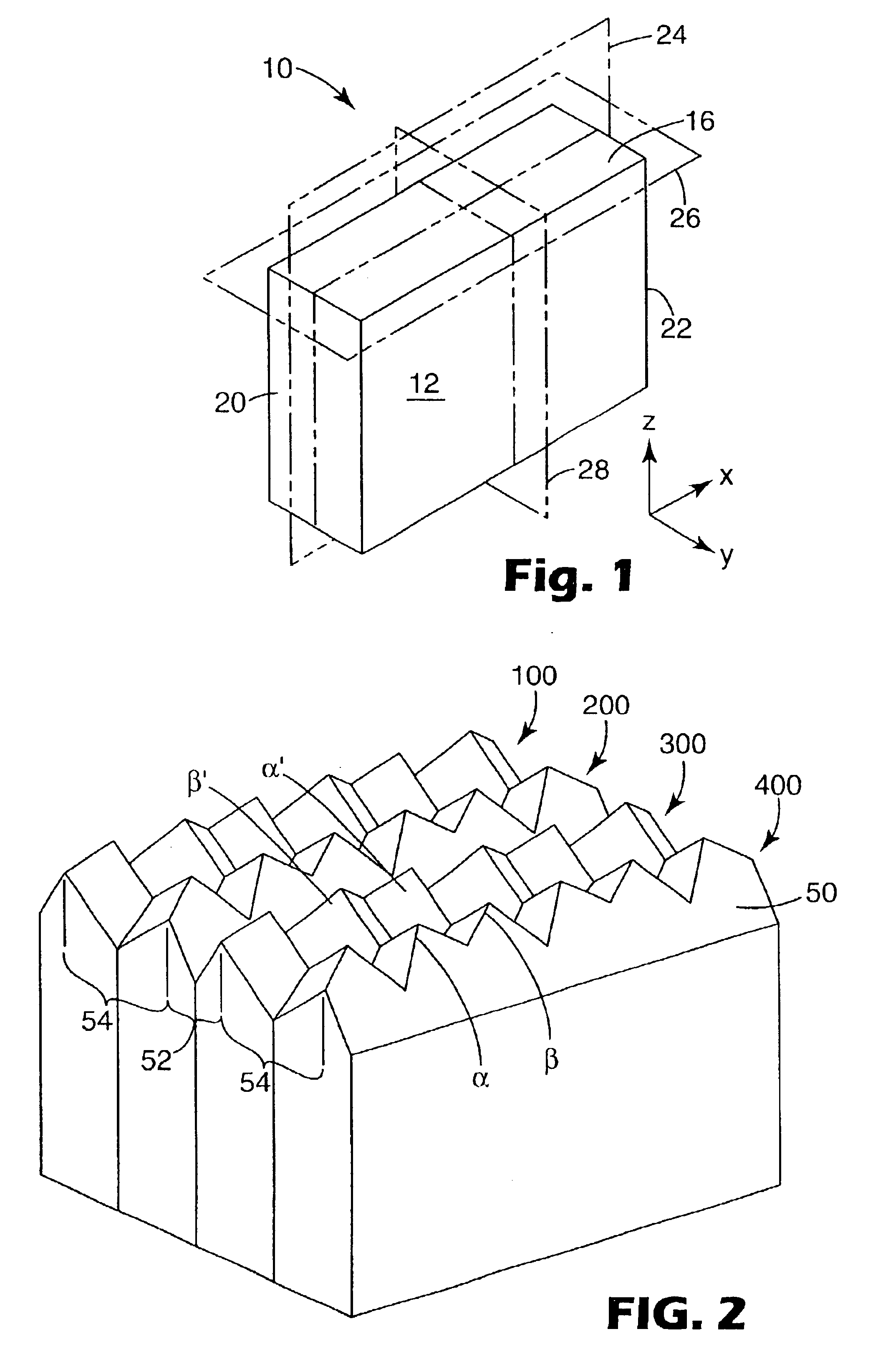
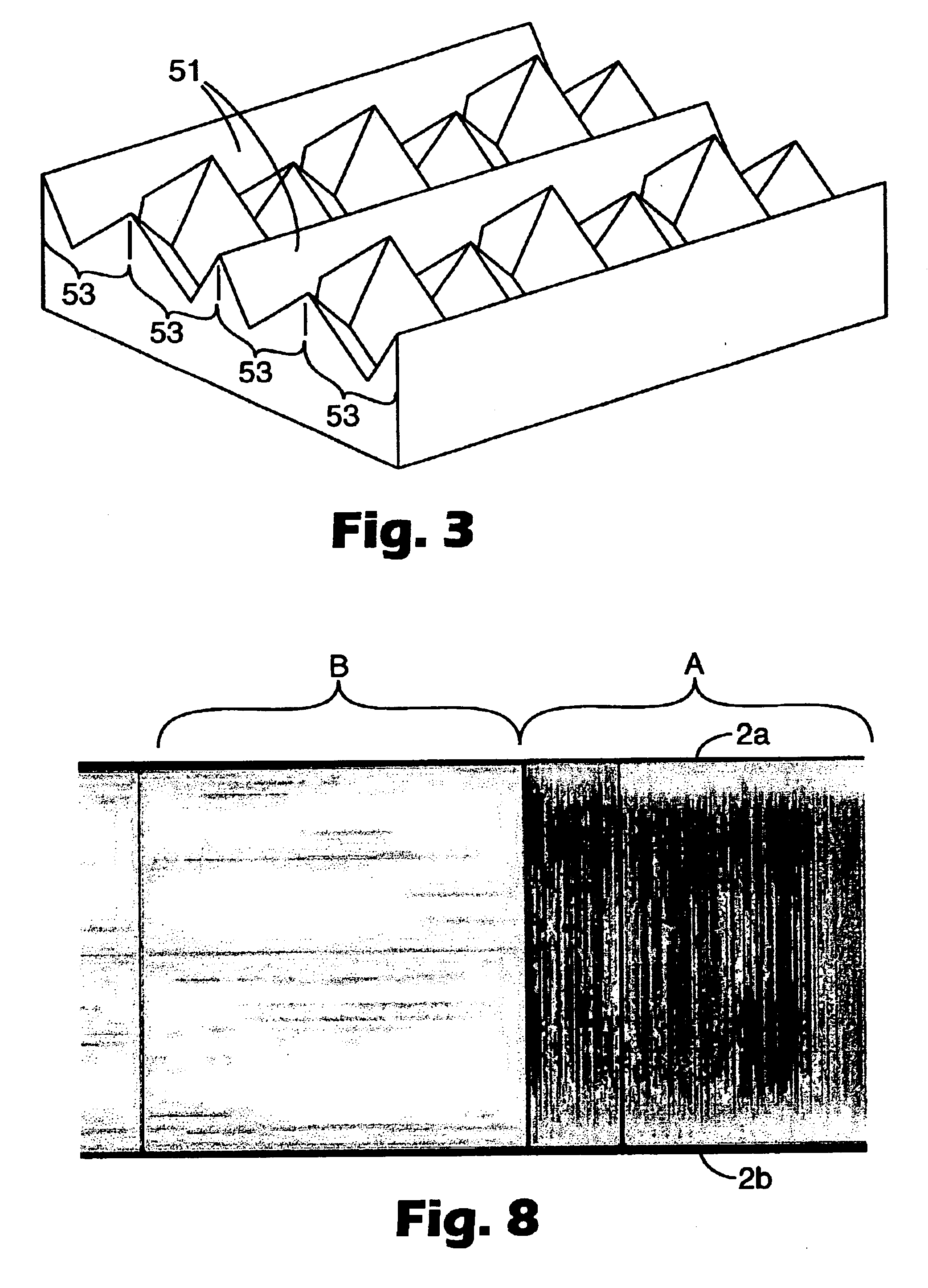
[0013]A characteristic of certain tools for making retroreflective sheeting comprising an array of full cube or PG cube corner cavities is the presence of channels. The present inventor has found that the presence of such channel as well as the orientation of such channels relative to the direction of relative motion of the tool in comparison to the resin delivery system (e.g. the advancing tool) during manufacture of sheeting has a significant effect on the quality of the replication as well as the rate of manufacturing the sheeting. The present invention relates to a method of making retroreflective sheeting providing a tool comprising a cube corner microstructured surface with at least one channel, advancing the tool in a direction such that the channel is substantially parallel to the direction of the advancing tool, casting a moldable resin onto said tool surface, solidifying the resin forming a retroreflective sheet having a surface comprising cube corner elements; and removing the sheet from the tool.

Problems solved by technology

A drawback to direct machining techniques, however, has been reduced design flexibility in the types of cube corner geometries that can be produced, which in turn affects the total light return.
However, it is difficult to maintain geometric accuracy with this multi-step fabrication process.
Design constraints may also be evident in the resulting PG cube corner elements and / or arrangement of elements.
Although described in the patent literature, retroreflective sheeting comprising an array of full cubes or PG cube corner elements has not been manufactured commercially or sold.

Method used


Image

  • Method of making retroreflective sheeting and articles
  • Method of making retroreflective sheeting and articles
  • Method of making retroreflective sheeting and articles

Examples


examples 1-4

[0079]Retroreflective sheeting was prepared utilizing a slot die apparatus that was substantially identical to a slot die apparatus commercially available from Extrusion Dies, Inc., Chippewa Falls, Wis. under the trade designation “Ultracoat” with the exceptions that the downstream die lip was changed to incorporate the following specific features: (1) the horizontal length of the lip was changed from 0.478″ to 0.884″; (2) a section of the lip near the polycarbonate exit slot was thinned to provide a hinge in the horizontal section of the lip, thereby allowing the downstream portion of the lip to be adjusted in a vertical plane; (3) the polycarbonate contacting surface of this lip was machined to provide two planar surfaces, the first surface being at an angle of 89.2 degrees to vertical as measured counterclockwise from the tool surface to an extrapolation of the parting line of the die, and the second surface being 87.6 degrees to vertical counterclockwise as measured counterclock...


PUM

PropertyMeasurementUnit
Microstructureaaaaaaaaaa
Thermoplasticityaaaaaaaaaa

Abstract

The invention relates to a method of making retroreflective sheeting and other articles prepared from casting a moldable synthetic resin onto a tool having a microstructured surface.

Description

RELATED APPLICATIONS[0001]This application claims priority to U.S. Patent Application Ser. No. 60 / 452,605 filed Mar. 6, 2003.FIELD OF THE INVENTION[0002]The invention relates to a method of making retroreflective sheeting prepared from casting a moldable synthetic resin onto a tool having a microstructured surface.BACKGROUND OF THE INVENTION[0003]Retroreflective materials are characterized by the ability to redirect light incident on the material back toward the originating light source. This property has led to the widespread use of retroreflective sheeting for a variety of traffic and personal safety uses. Retroreflective sheeting is commonly employed in a variety of articles, for example, road signs, barricades, license plates, pavement markers and marking tape, as well as retroreflective tapes for vehicles and clothing.[0004]Two known types of retroreflective sheeting are microsphere-based sheeting and cube corner sheeting. Microsphere-based sheeting, sometimes referred to as “b...

Claims


Application Information

Patent Timeline
IPC IPC(8): B29D11/00G02B5/124G02B5/12E01F9/615
CPCB29D11/00605G02B5/124Y10T428/2457Y10S359/90B29D11/00G02B5/122B29K2069/00
Inventor SMITH, KENNETH L.
Owner 3M INNOVATIVE PROPERTIES CO
Learn More