Method for generating an electric current within a tire

a technology of electric current and tire, which is applied in the field of tires, can solve the problems of general suitability for inclusion in elastomeric components, and achieve the effect of increasing the linked magnetic flux and increasing the magnetic permeability

Inactive Publication Date: 2005-04-26
PIRELLI TYRE SPA
View PDF29 Cites 25 Cited by
  • Summary
  • Abstract
  • Description
  • Claims
  • Application Information

AI Technical Summary

Benefits of technology

[0025]The applicant has further discovered that the user circuits may also advantageously be mounted, with the secondary inductive element, on a structural member which is substantially free of large deformations, such as the reinforcing bead core of the bead.

Problems solved by technology

The bead core is in fact the least deformable structural member of the tire and is therefore well suited for use as the base for mounting electronic devices for sensing and transmitting signals, these devices, owing to their rigidity, fragility and sensitivity, not being generally suitable for inclusion in elastomeric components subject to large deformations.

Method used


Image

  • Method for generating an electric current within a tire
  • Method for generating an electric current within a tire
  • Method for generating an electric current within a tire

Examples


Embodiment Construction

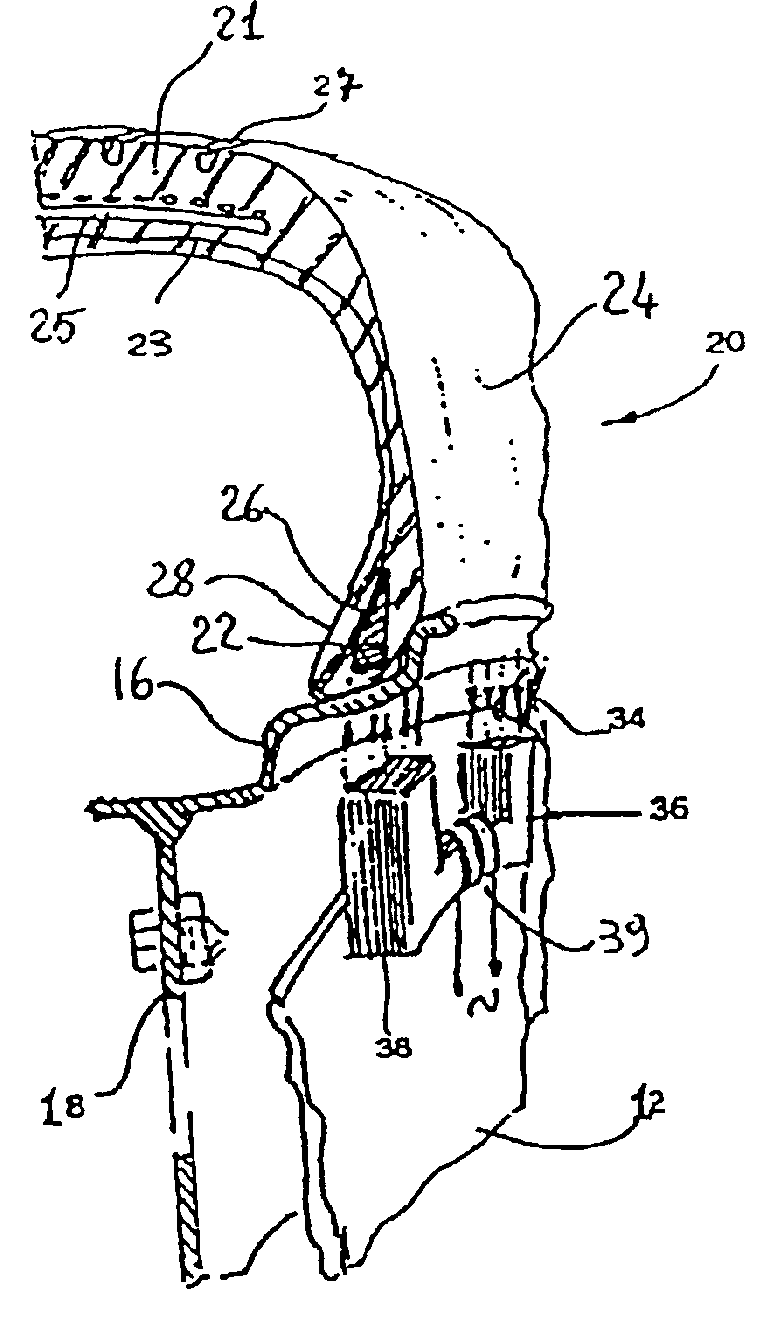
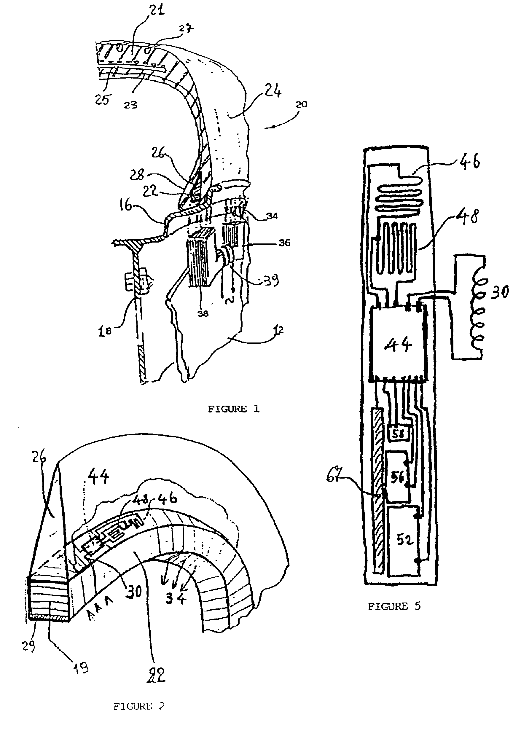
[0053]With reference to FIG. 1, a tire 20 comprises a carcass of toroidal form, which has a central crown portion 21 from whose edges two axially opposing sidewalls 24 extend radially inwards and terminate in annular areas of high rigidity 28, usually known as beads, each of these being reinforced with at least one inextensible annular reinforcing core 22, usually known as a bead core.

[0054]The supporting structure of the said carcass comprises at least one reinforcing ply 23, each of whose opposing lateral flaps is fixed to a corresponding bead core 22, for example by wrapping it from the inside outward around the said bead core. On the outer peripheral edge of each bead core there is usually applied an annular elastomeric filling 26, of substantially triangular section, usually called the “bead filler”, which occupies the space formed between the reinforcing ply and the corresponding wrapped around lateral flap.

[0055]As already stated, the axially opposing areas of the tire compri...


PUM

PropertyMeasurementUnit
breaking strainaaaaaaaaaa
tensile strengthaaaaaaaaaa

Abstract

A method for generating an electric current within a tyre includes the step of including a variable magnetic field in at least one winding. The tire includes at least one bead core and the at least one winding. The at least one winding includes at least one turn wound around the at least one bead core. The electric current may power one or more electronic devices. The one or more electronic devices may include means for sensing one or more parameters associated with the tire, such as temperature sensors, pressure sensors, or a pair of extensometers orientated perpendicularly to each other to sense deformations of the at least one bead core. The at least one winding may form at least part of a first inductive element associated with and movable with respect to at least one second inductive element to form an electrical generator.

Description

CROSS-REFERENCE TO RELATED APPLICATIONS[0001]This application is a divisional of U.S. patent application Ser. No. 09 / 263,500, filed Mar. 8, 1999 now U.S. Pat. No. 6,470,933, in the U.S. Patent and Trademark Office, the contents of which are relied upon and incorporated herein by reference; additionally, Applicant claims the right of priority under 35 U.S.C. §119(a)-(d) based on patent application Ser. No. 98830122.2, filed Mar. 9, 1998, in the European Patent Office; further, Applicant claims the benefit under 35 U.S.C. §119(e) based on prior-filed, copending provisional application No. 60 / 086,508, filed May 22, 1998, in the U.S. Patent and Trademark Office.BACKGROUND OF THE INVENTION[0002]1. Field of the Invention[0003]The present invention relates to a tire for use on motor vehicles, trailers, motorcycles, aircraft or similar (referred to generally as “vehicles” in the following text), provided with an electricity generator which can supply sensors and any other circuits incorpora...

Claims


Application Information

Patent Timeline
Patent Type & Authority Patents(United States)
IPC IPC(8): B29D30/06B29D30/48B60C19/00B60C15/04B60C23/04B60C23/02
CPCB29D30/48B60C15/04B60C19/00B60C23/0408B60C23/0433B60C23/041Y10T152/10819B60C2019/005Y10T152/10846
Inventor VOLPI, ALESSANDRO
Owner PIRELLI TYRE SPA
Why Eureka
Try Eureka