

Funnel for color cathode ray tube
a color cathode ray tube and tunnel technology, applied in the direction of cathode-ray/electron-beam tube electrical connection, electric discharge tube/lamp manufacture, electric discharge tube/lamp manufacturing, etc., can solve the problems of reducing the sealing strength of the cathode tube. , to achieve the effect of suppressing the formation of unnecessary lapping scratches and convenient and preferabl
- Summary
- Abstract
- Description
- Claims
- Application Information
AI Technical Summary
Benefits of technology
Problems solved by technology
Method used
Image

Examples
Embodiment Construction
[0030]Now the embodiments of the present invention will be described below with reference to the accompanying drawings. The members and portions being substantially the same as those described earlier in this specification have the same numerals and symbols throughout the figures.
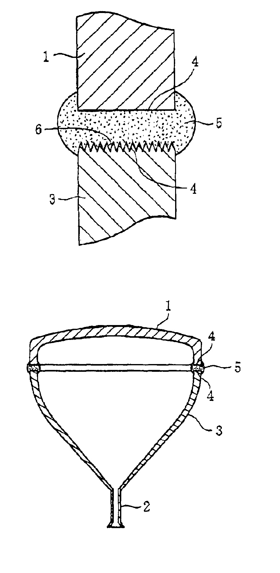
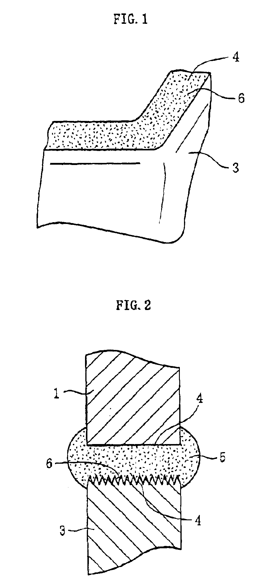
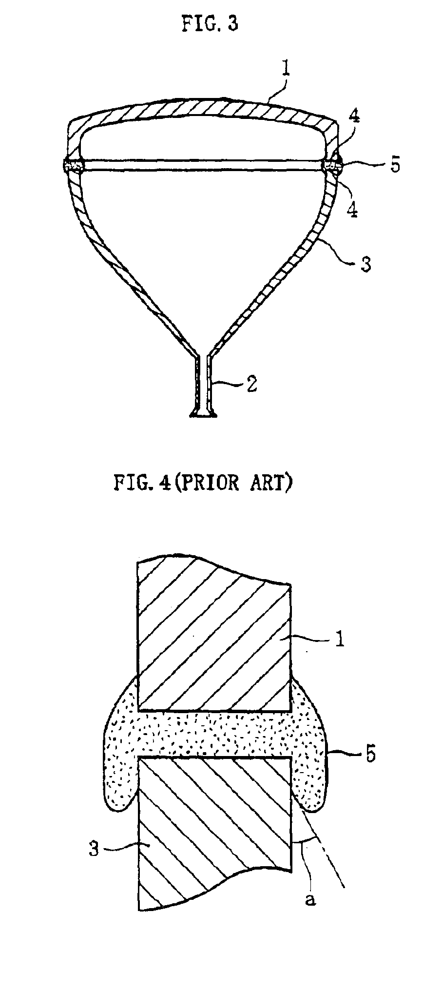
[0031]FIG. 1 is an enlarged perspective view of a part of a funnel 3 for a color cathode ray tube in accordance with an embodiment. The funnel 3 has a rough surface 6 extending whole circumference of a seal end surface 4. Rz and Sm of the rough surface 6 meet the conditions of 10≦Rz≦25 μm and 2.56 has profile peaks 6a that are convex with respect to a mean line m, profile valleys 6b that are concave with respect to the mean line m and a plurality of dimple-like micro cavities 6c formed by the profile peaks 6a and the profile valleys 6b.
[0032]Such rough surface 6 can be made by, for example, pressing the seal end surface 4 of the funnel 3 onto a rotating grind table, and grinding the seal end surface 4 unde...
PUM
 Abstract
Description
Claims
Application Information