Resonant circuit for increasing variable reluctance sensor output

a variable reluctance and output technology, applied in adaptive control, computer control, instruments, etc., can solve the problems of low signal-to-noise ratio, substantial high-frequency electrical noise produced by other engine components, and various problems of related art vrs

Inactive Publication Date: 2005-04-26
CATERPILLAR INC
View PDF4 Cites 2 Cited by
  • Summary
  • Abstract
  • Description
  • Claims
  • Application Information

AI Technical Summary

Benefits of technology

[0009]Further, in accordance with an embodiment of the present invention, there is provided machine system that includes a machine and a sensing system electrically coupled to the machine. The sensing system includes a variable reluctance sensor (VRS) adapted to detect a position of a gear tooth mounted on a camshaft wheel of the machine, and to generate a basic output signal having a variable amplitude and a basic frequency representative of the machine characteristic. The sensing system also includes a first switching device electrically ...

Problems solved by technology

However, the related art VRS has various problems and disadvantages.
Typically, there is substantial high-frequency electrical noise produced by other engine components (e.g., firing injectors or local power supplies on-board the engine).
Thus, at low speeds th...

Method used


Image

  • Resonant circuit for increasing variable reluctance sensor output
  • Resonant circuit for increasing variable reluctance sensor output

Examples


Embodiment Construction

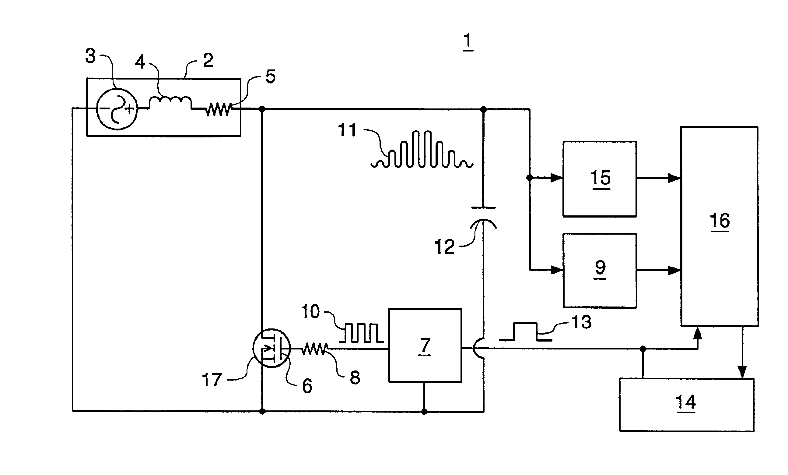
[0013]An exemplary embodiment of the present invention provides an apparatus and method of more accurately sensing machine characteristics during a start-up phase of a machine and during normal operation of the machine. The following description uses a vehicle engine as an example only. As would be understood by one skilled in the art, this invention also is applicable to other types of machines having a rotating member.

[0014]FIG. 1 illustrates a schematic diagram of an apparatus as represented by a circuit 1 that measures a characteristic of a machine. The circuit 1 may be coupled to the machine, or it may be incorporated into the machine. The circuit 1 includes a variable reluctance sensor (VRS) 2. The VRS 2 generates a basic output signal having a variable amplitude and a basic frequency being representative of the characteristic of the machine. While the VRS 2 is preferably implemented as a single fine-wire coiled about a magnetic structure (e.g., permanent magnet), the circuit ...


PUM


Abstract

An apparatus and method for measuring a characteristic of a machine. A variable reluctance sensor (VRS) is coupled to the machine. A first switching device and capacitor, coupled in parallel with the VRS, boosts a variable amplitude of a basic output signal generated by the VRS to increase the signal-to-noise ratio. A control input of the first switching device receives signals, and a modified output signal is generated by the first switching device, having a variable amplitude that is substantially higher than the variable amplitude of the VRS. The modified output signal has an increased signal-to-noise ratio such that machine speed can be more accurately measured during a start-up phase.

Description

TECHNICAL FIELD[0001]The present invention relates generally to a variable reluctance sensor (VRS) for use in a fuel combustion engine, and more particularly to a VRS that operates at low engine speed to more accurately detect gear tooth position and measure engine speed.BACKGROUND[0002]In the related art, a variable reluctance sensor (VRS) is described in U.S. Pat. No. 5,726,888, which discloses a method and system for testing a wheel speed sensor input circuit in an anti-braking system (ABS) and / or traction control (TC) system. Alternatively, a VRS, such as the VRS manufactured by Electro Corp., may be used to measure engine speed.[0003]The conventional VRS is a coil of wire wrapped around a permanent magnet, with leads for connection into a circuit. Typically, the VRS is in the form of a head that is positioned adjacent a rotatable gear or the like. Thus, when the ferrous metal of a tooth of a gear moves past the sensor head, the magnetic field is altered, and a voltage is induce...

Claims


Application Information

Patent Timeline
IPC IPC(8): G01P3/46G01B7/30G01P3/42G01P3/488G05B15/00G05B13/02G05B21/00G05B21/02
CPCG01P3/488
Inventor WILD, ARTHUR
Owner CATERPILLAR INC
Why Eureka
Try Eureka