Hybrid mode stirred and mode tuned chamber

a technology of electromagnetic field and stirred chamber, which is applied in the direction of measuring interference from external sources, measuring devices, instruments, etc., can solve the problems of less than ideal known chambers, and it is generally not feasible to build a test chamber of anything near this size, so as to improve the uniformity of electromagnetic energy.

Inactive Publication Date: 2005-04-26
INST OF HIGH PERFORMANCE COMPUTING
View PDF8 Cites 12 Cited by
  • Summary
  • Abstract
  • Description
  • Claims
  • Application Information

AI Technical Summary

Benefits of technology

[0008]The invention resides in a novel electromagnetic test chamber. The chamber includes an electromagnetic shield that defines an interior volume for the conduction of electromagnetic field exposure and radiation testing. An electrically conductive rod is provided inside the interior volume. The rod can be energized to generate electromagnetic radiation inside the interior volume, and moved through the interior volume to change the characteristics of the electromagnetic field over a working volume inside the electromagnetic shield. In preferred embodiments, the energy applied to the rod is controlled in a manner that enhances uniformity of the electromagnetic energy within the working volume as the rod moves through the interior volume. Some embodiments will include a paddle stirrer inside the interior volume of the chamber, to further stir and modify the electromagnetic field inside the chamber.
[0009]Preferred embodiments will include a second electrically conductive rod inside the chamber, and apparatus operable to energize that rod as well as the first one. In a particularly preferred embodiment, the first and second rods are mounted inside the chamber at right angles to one another, the first rod is movable through the interior volume in a first direction that is perpendicular to its long axis, and the second rod is movable through the chamber in a second direction that is perpendicular both to its own long axis and to the first rod's direction of motion. In that embodiment, the apparatus that energizes the rods controls the energy supplied to the two rods so as to enhance the uniformity of the electromagnetic field applied to a working volume inside the chamber as the two rods move through the chamber.

Problems solved by technology

Known chambers are less than ideal, however, particularly for testing for electromagnetic radiation at relatively low frequencies.
It is obviously not generally feasible to build a test chamber of anything near this size.

Method used


Image

  • Hybrid mode stirred and mode tuned chamber
  • Hybrid mode stirred and mode tuned chamber
  • Hybrid mode stirred and mode tuned chamber

Examples


Embodiment Construction

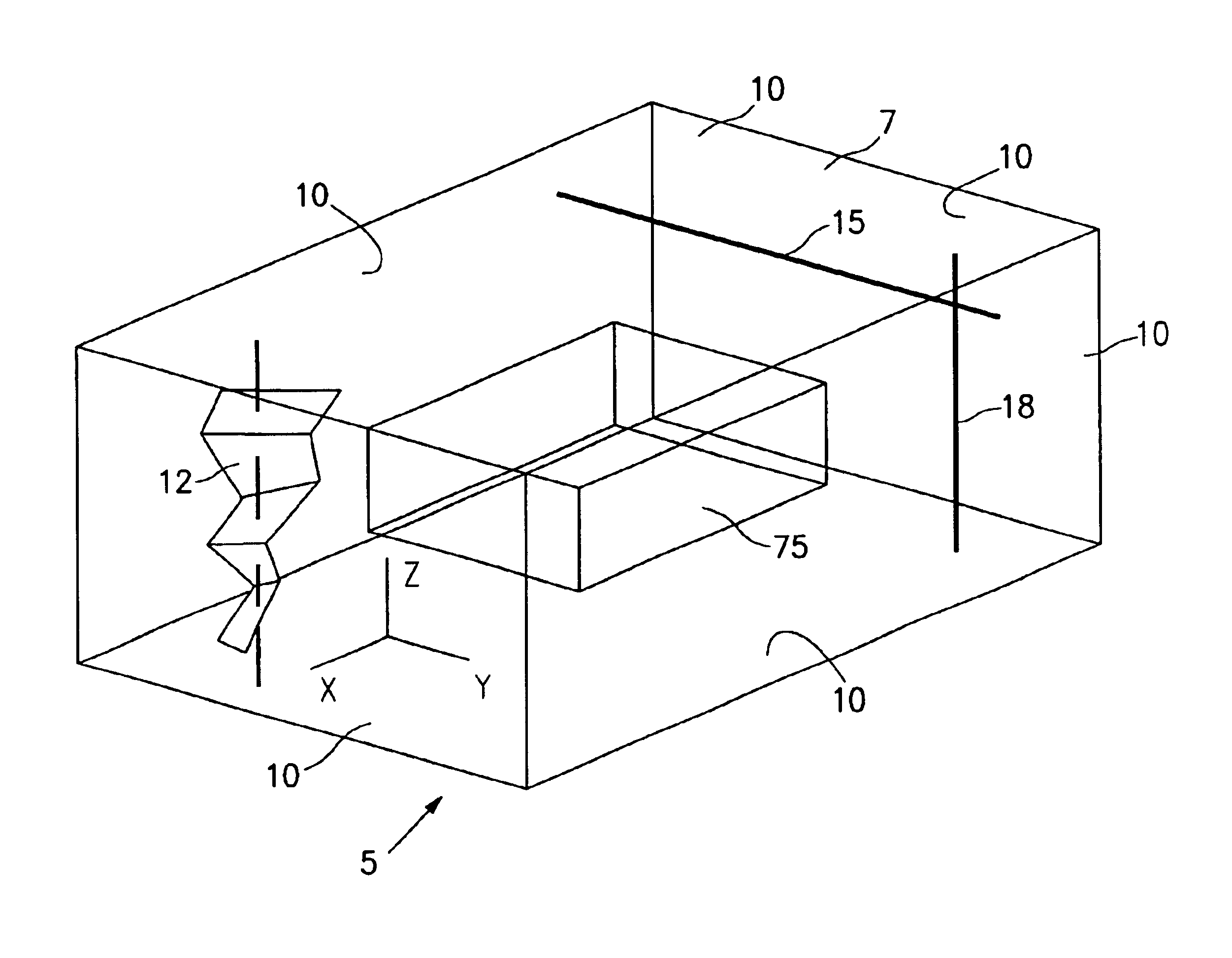
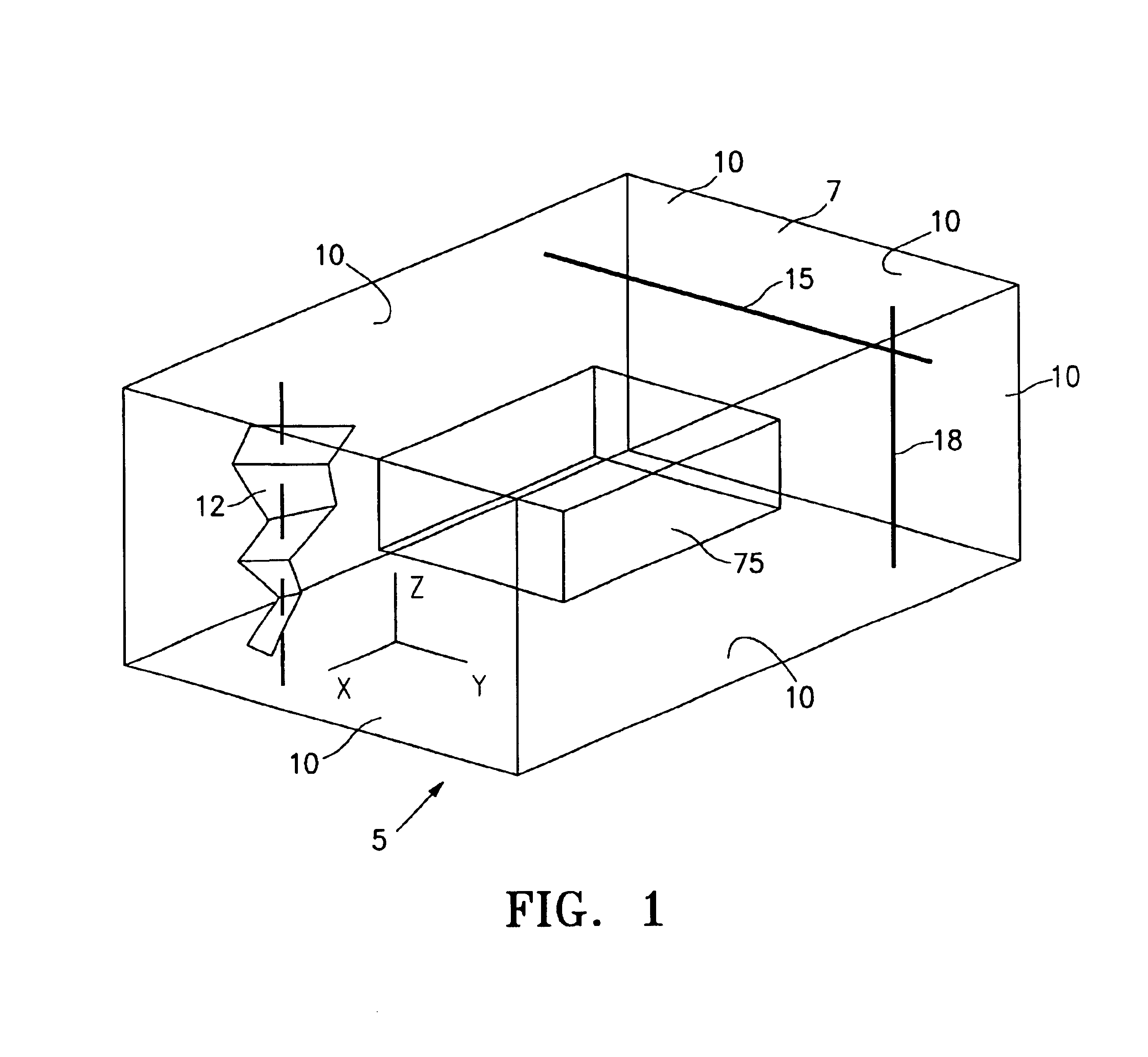
[0015]FIG. 1 is a schematic drawing illustrating an electromagnetic test chamber 5 according to the present invention. The test chamber includes an enclosure 7, which includes walls 10 situated to enclose an interior volume.

[0016]The walls of the test chamber are formed of aluminum or another material that isolates the interior volume from the exterior environment, so that the enclosure serves as an electromagnetic reverberation chamber suitable for testing electronic devices for susceptibility to external electromagnetic radiation. Such a chamber may also be used to measure the extent to which an electronic device leaks or emits electromagnetic radiation into the environment.

[0017]A twisted Z-shaped paddle stirrer 12 is located inside the test chamber 5, near one of the chamber's corners. The paddle stirrer rotates to change boundary conditions and thereby to “stir” electromagnetic fields present inside the test chamber. For high frequency electromagnetic radiation, the stirrer pro...


PUM


Abstract

First and second electrically conductive rods are provided inside a shielded electromagnetic test chamber. These rods are energized to radiate electromagnetic energy inside the chamber. The rods are mounted inside the chamber at right angles to one another, the first rod is movable through the interior volume in a first direction perpendicular to its long axis, and the second rod is movable through the chamber in a second direction perpendicular both to its own long axis and to the first rod's direction of motion. Energy is supplied to the two rods in a way that enhances the uniformity of the electromagnetic field applied to a working volume inside the chamber as the two rods move through the chamber.

Description

BACKGROUND OF THE INVENTION[0001]The invention relates generally to electromagnetic field testing. More particularly, the invention provides improved mode stirred electromagnetic field test chambers and associated methods for electromagnetic field testing in such chambers.[0002]Mode stirred chambers are used for testing electromagnetic compatibility of electronic devices and the susceptibility of electronic devices to electromagnetic radiation found in the devices' operating environments. In such testing, it is necessary to isolate the equipment being tested from electromagnetic fields that would otherwise be present in the test environment, so that electromagnetic fields can be applied to the equipment under test (EUT) in a controlled way. The performance of the EUT can then be assessed based on the known electromagnetic fields that are applied to it.[0003]Isolation chambers have been used to shield EUT from external electromagnetic fields. Such chambers include electrically conduc...

Claims


Application Information

Patent Timeline
Patent Type & Authority Patents(United States)
IPC IPC(8): G01R31/00
CPCG01R31/002G01R31/001
Inventor LI, ERPINGWANG, SHENGZHANG, DAMING
Owner INST OF HIGH PERFORMANCE COMPUTING
Why Eureka
Try Eureka