
Saliency-based position estimation in permanent magnet synchronous motors

a synchronous motor and position estimation technology, applied in the direction of motor/generator/converter stopper, dynamo-electric gear control, dynamo-electric converter control, etc., can solve the problems of high cost of sensor, fragile, etc., and achieve the effect of reducing the cost of maintenance and repair of the system, and reducing the actual cost of production of the produ

Inactive Publication Date: 2005-04-26
NORTHEASTERN UNIV
View PDF9 Cites 21 Cited by
  • Summary
  • Abstract
  • Description
  • Claims
  • Application Information

AI Technical Summary

Benefits of technology

"The patent describes a method and system for estimating the state of a motor without using sensors. The method involves measuring the motor's current and voltage and converting them into α-β coordinates. A least square estimator is then used to estimate the motor's parameters, specifically the inductances, which change with the rotor position. These estimated inductances are then used to drive a state observer, which provides an estimate of the motor's mechanical subsystem, including its position, velocity, and acceleration. The technical effect of this invention is to enable the accurate and efficient control of motors without the need for expensive and difficult-to-install sensors."

Problems solved by technology

These sensors typically are expensive, require careful installation and alignment, and are fragile.
Accordingly, the the use of these position sensors both in terms actual cost to produce the product and in the costs associated with the maintenance and repair of these systems is high.
Sensorless position estimation systems have been developed to overcome these limitations, but the present sensorless position estimation systems have their own drawbacks as well.
Although this method achieves valid results at higher rotational velocities, at low rotational velocities and high torque settings, the back emf voltage signal decreases to values that are too small to be useful, and vanish entirely at speeds close to a standstill.
Thus, the back emf method is not suitable for these low rotational velocity high torque applications.
Although this method avoids the singularities of the back emf method, these methods are computationally intensive and thus are not well suited for industrial applications.

Method used


Image

  • Saliency-based position estimation in permanent magnet synchronous motors
  • Saliency-based position estimation in permanent magnet synchronous motors
  • Saliency-based position estimation in permanent magnet synchronous motors

Examples


Embodiment Construction

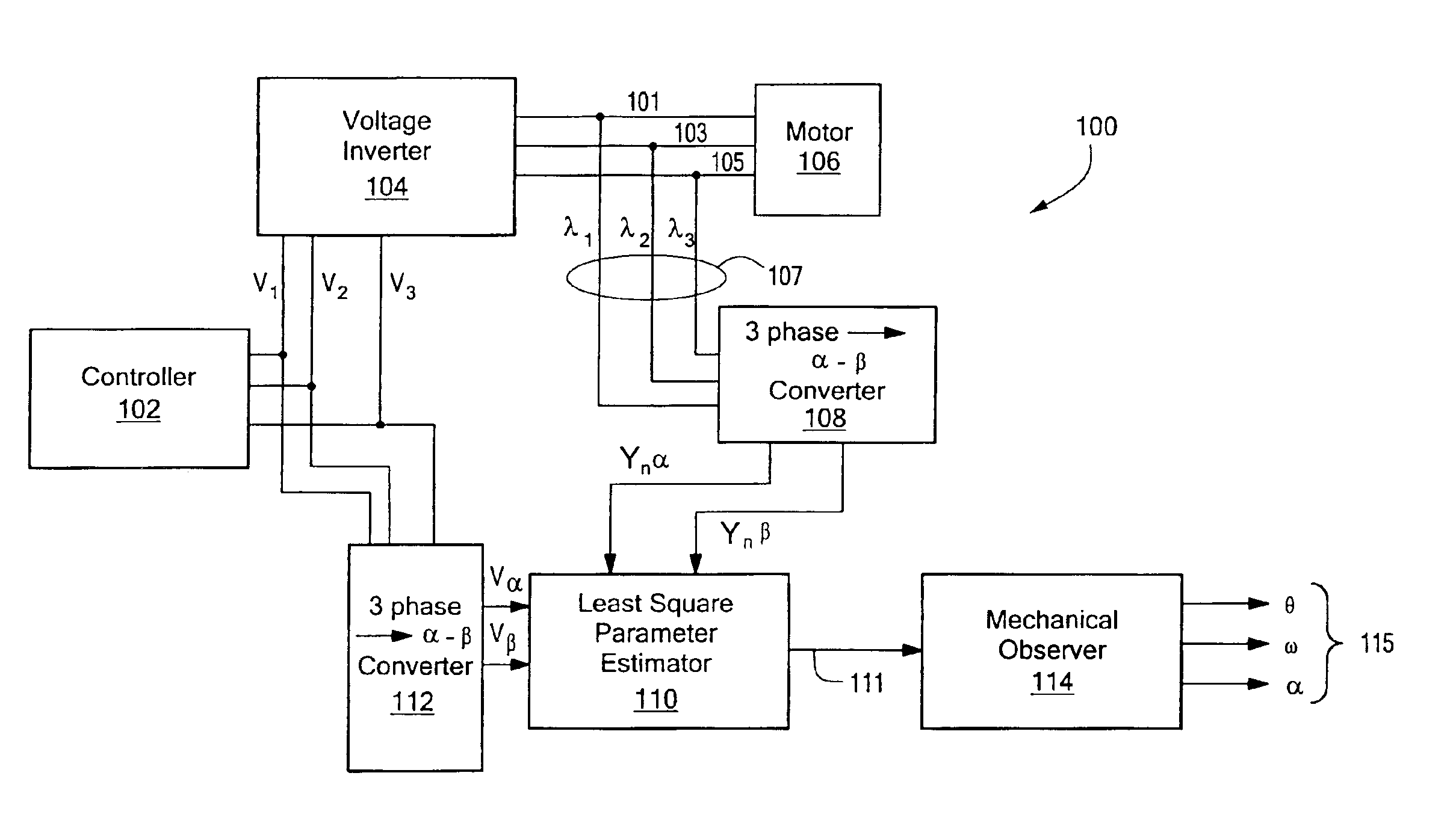
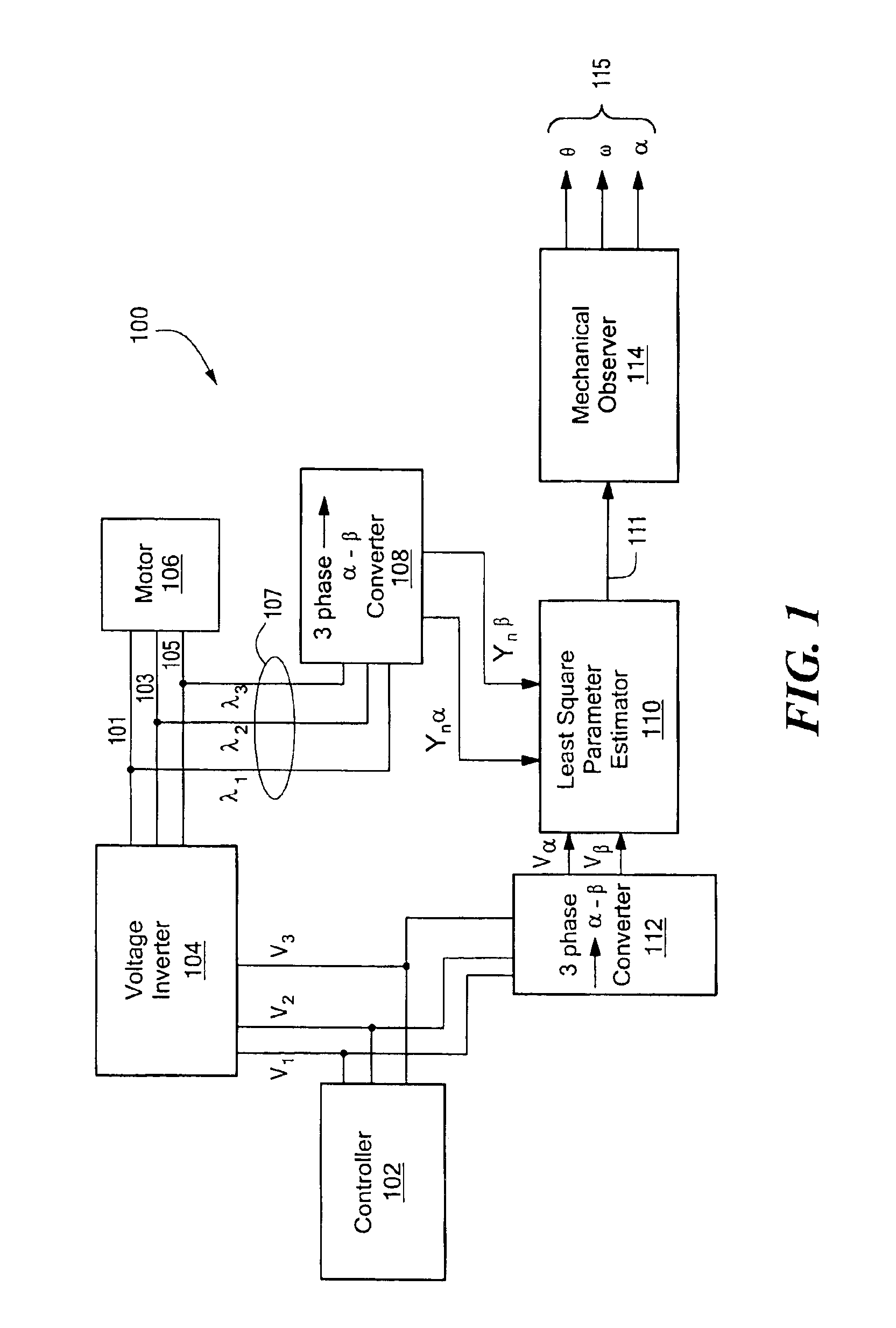
[0014]FIG. 1 depicts a block diagram of one embodiment of the sensorless position estimation system (“system”). The system 100 includes a controller 102 providing 3 phase PWM control signals to a voltage inverter 104 that is responsive to the PWM control signals by providing the appropriate phasing to the three currents 101, 103, 105 to the motor 106. The three currents 101, 103, and 105 are sensed by current sensor 107 and provided to a 3-phase to α-β converter module 108. The converter module 108 transforms the 3-phase currents into 2 phases and provides iα and iβ values using the well standard transformation: [yαyβ]=23⁡[112-12032-32]⁢ [x1x2x3]

where yα and yβ are the output in α-β coordinates and x1, x2, and x3 are the 3 polyphase current values. The α-β currents, yαand yβ, are then provided to the least square parameter estimator 110.

[0015]The controller 102 also provides the 3-phase PWM control signals to another 3-phase to α-β converter module 112 that converts the 3-phase volt...


PUM


Abstract

A method and system for the sensorless estimation of the states of the mechanical subsystem of a motor are disclosed. In particular, the method and system split the estimation problem into two sub-problems: the estimation of motor parameters as a function of position, and the determination of the states of the mechanical subsystem of the motor using the estimated parameters via a state observer. Motor current and PWM voltage in a polyphase system is measured or otherwise determined and converted into current and voltage in α-β coordinates. A least square estimator is constructed that uses the voltage and current in α-β coordinates and provides an estimate of the motor parameters, and in particular, the inductances of the motor, which are a function of the rotor position. These estimated inductances are used to drive a state observer whose dynamics have been selected to provide as an output the state of the mechanical subsystem of the motor, and in particular, the position, velocity, and acceleration of this subsystem.

Description

CROSS REFERENCE TO RELATED APPLICATIONS[0001]This application claims the priority of U.S. Provisional Patent Application No. 60 / 366,047 filed, Mar. 20, 2002 entitled SALIENCY-BASED POSITION ESTIMATION IN PM SYNCHRONOUS MOTORS, the whole of which is hereby incorporated by reference herein.STATEMENT REGARDING FEDERALLY SPONSORED RESEARCH OR DEVELOPMENT[0002]Part of the work leading to this invention was carried out with United States Government support provided under a grant from the Office of Naval Research, Grant No. N00014-97-1-0704 and under a grant from the National Science Foundation, Grant No. EC9502636 Therefore, the. U.S. Government has certain rights in this invention.BACKGROUND OF THE INVENTION[0003]This invention relates generally to motor position estimation systems and in particular to motor position estimation systems for permanent magnet synchronous motors.[0004]Permanent magnet synchronous motors (PMSMs) have become increasingly popular in high-performance variable-fr...

Claims


Application Information

Patent Timeline
Patent Type & Authority Patents(United States)
IPC IPC(8): G01P3/42G01P3/44H02P21/14
CPCH02P21/146G01P3/44H02P21/18
Inventor PETROVIC, VLADANSTANKOVIC, ALEX M.
Owner NORTHEASTERN UNIV
Learn More