Gas turbine fuel pilot nozzle

a technology of pilot nozzle and gas turbine, which is applied in the ignition of turbine/propulsion engines, engine starters, lighting and heating apparatus, etc., can solve the problems of engine shutdown and extensive repairs, and the device cannot be readily applied to the fuel nozzle, so as to increase the wall thickness and increase the stiffness

Inactive Publication Date: 2005-05-03
H2 IP UK LTD
View PDF7 Cites 30 Cited by
  • Summary
  • Abstract
  • Description
  • Claims
  • Application Information

AI Technical Summary

Benefits of technology

[0007]According to the present invention, a pilot fuel nozzle configuration is disclosed having a natural frequency sufficiently outside the range of the operating frequencies of a gas turbine engine to avoid resonance. Multiple embodiments of the present invention are disclosed depending on whether the pilot fuel nozzle is newly manufactured, is a repair to an existing pilot nozzle, or depending on the desired natural frequency for the pilot nozzle. The pilot fuel nozzle includes an elongated housing, first and second flanges, and a nozzle tip, with the first flange fixed to the elongated housing at a first end and the nozzle tip fixed to the second end, opposite of the first end. The second flange is fixed along the elongated housing and is used for attaching the pilot fuel nozzle to a combustor. The present invention incorporates an increased wall thickness along at least a mid-span portion of the pilot nozzle to increase the stiffness and change the natural frequency.
[0008]It is an object of the present invention to provide a pilot fuel nozzle having a natural frequency sufficiently out of the range of an operating frequency of a gas turbine engine such that resonance and potentially damaging cracks to the pilot nozzle are avoided.

Problems solved by technology

Field experience with a pilot fuel nozzle of the configuration shown in FIG. 1 includes severe fractures that have liberated portions of nozzle 14 causing significant damage to the combustor and turbine sections of the engine, forcing engine shutdown and extensive repairs.
Unfortunately, this device cannot be readily applied to a fuel nozzle comprised of a single tube cantilevered in a combustor since the fuel nozzle structure is not configured to utilize a damper.

Method used


Image

  • Gas turbine fuel pilot nozzle
  • Gas turbine fuel pilot nozzle
  • Gas turbine fuel pilot nozzle

Examples


Embodiment Construction

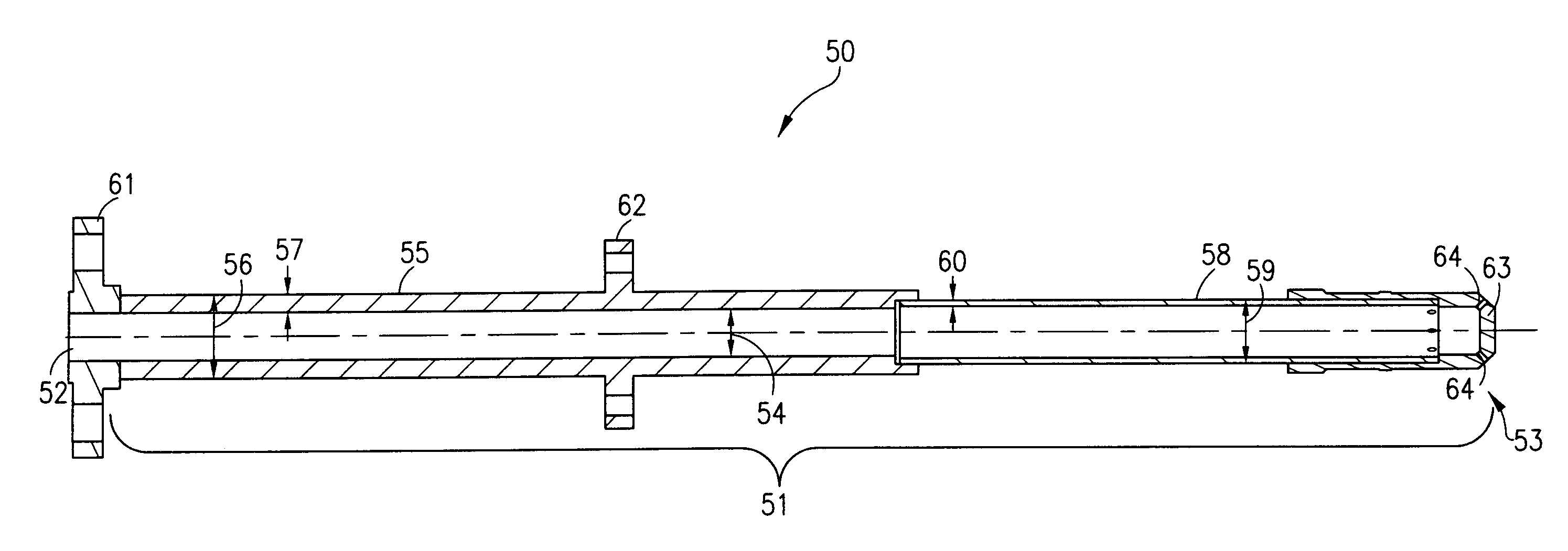
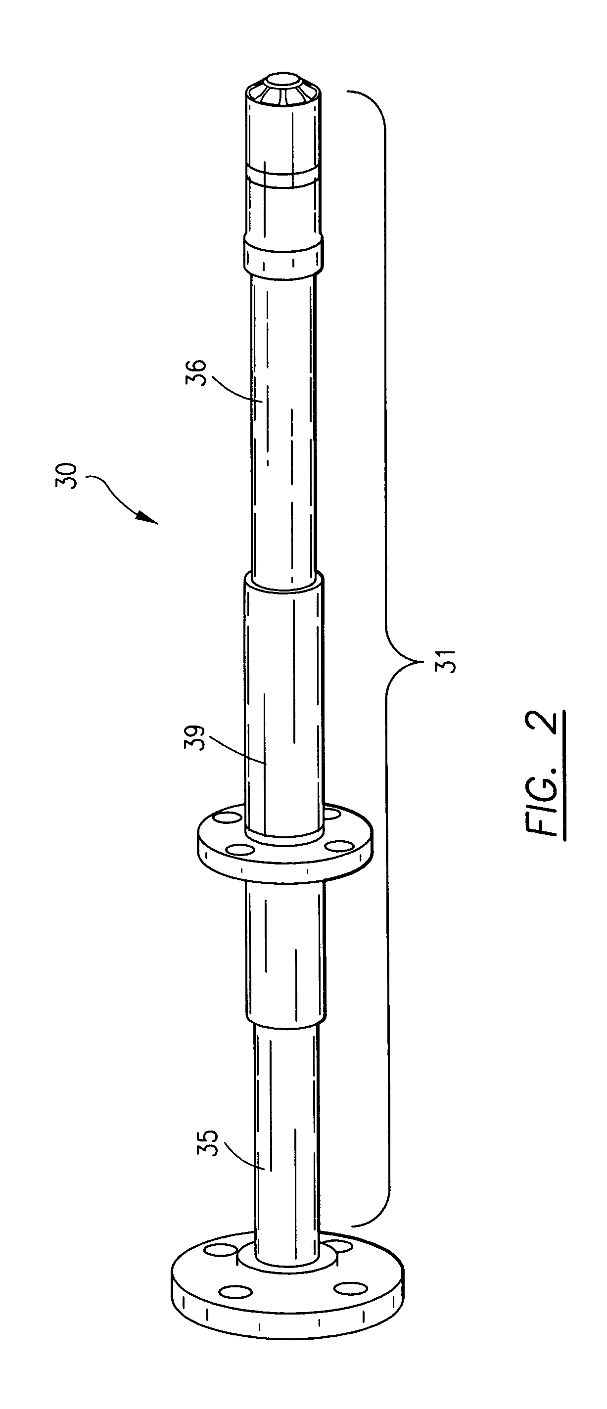
[0015]The preferred embodiment of the present invention is shown in detail in FIGS. 2 and 3. A pilot fuel nozzle 30 for use in a gas turbine combustor comprises an elongated housing 31 generally circular in cross section, with housing 31 extending from a first end 32 to a second end 33. Elongated housing has a center axis, a length, and a first inner diameter 34, each of which extend from first end 32 to second end 33. In the preferred embodiment, elongated housing 31 comprises three portions. First portion 35 and second portion 36 each have a first outer diameter 37, thereby forming a first wall thickness 38 between first inner diameter 34 and first outer diameter 37. Located inbetween first portion 35 and second portion 36 is a third portion 39 having a second outer diameter 40, and thereby forming a second wall thickness 41 between first inner diameter 34 and second outer diameter 40. Pilot fuel nozzle 30 further comprises a plurality of flanges for connecting the nozzle to a fu...


PUM


Abstract

A pilot fuel nozzle configuration for use in a combustor is disclosed having a natural frequency outside the range of the operating frequencies of a gas turbine engine. Multiple embodiments are disclosed for the improved pilot fuel nozzle including configurations for newly manufactured nozzles, repair to existing pilot nozzles, as well as multiple natural frequency levels for the improved pilot fuel nozzle. The pilot fuel nozzle comprises an elongated housing, first and second flanges, and a nozzle tip, with the first flange fixed to the elongated housing at a first end and the nozzle tip fixed to the second end, opposite of the first end. The second flange is fixed along the elongated housing and is used for attaching the pilot fuel nozzle to a combustor. The present invention incorporates an increased wall thickness along at least a mid-span portion of the pilot nozzle to increase the stiffness and change the natural frequency.

Description

TECHNICAL FIELD[0001]This invention relates to a pilot fuel nozzle for a gas turbine combustor and more specifically to a particular nozzle structure having an altered natural frequency and a method for altering the natural frequency of a pilot fuel nozzle.BACKGROUND OF THE INVENTION[0002]A gas turbine engine contains a compressor in fluid communication with a combustion system, where the combustion system often contains a plurality of combustors arranged about the engine. The compressor raises the pressure of the air passing through each stage of the compressor and directs it to the combustors where fuel is injected and mixed with the compressed air. The fuel and air mixture ignites and combusts creating a flow of hot gases that are then directed into the turbine. The hot gases drive the turbine, which in turn drives the compressor, and for electrical generation purposes, also drives a generator.[0003]Most combustion systems utilize a plurality of fuel injectors for staging, emissi...

Claims


Application Information

Patent Timeline
Patent Type & Authority Patents(United States)
IPC IPC(8): F02C7/22
CPCF02C7/22F23R3/343F23R3/286
Inventor SOBIESKI, PETER A.SMITH, KELLY SHAWNLOVELACE, ALANRIZKALLA, HANY
Owner H2 IP UK LTD
Why Eureka
Try Eureka