Buoyancy flushing apparatus and method thereof

a technology of flushing apparatus and buoyancy, which is applied in the direction of operating means/releasing devices of valves, sewage draining, water supply installation, etc., can solve the problems of float to loose buoyancy, sink to the bottom of the tank, and not provide a great flexibility in relation,

Inactive Publication Date: 2005-05-03
PREMIER TECH EAU & ENVIRONNEMENT LTEE
View PDF25 Cites 21 Cited by
  • Summary
  • Abstract
  • Description
  • Claims
  • Application Information

AI Technical Summary

Benefits of technology

[0019]The guiding means preferably comprises an upright rod with a lower end connected to a bottom wall of the outlet chamber, the valve being mounted on the rod in a slidable manner. The guiding means also preferably comprises:
[0020]a sleeve slidably mounted on the upright rod, the ballast unit being fixed to the sleeve, whereas the float unit is slidably mounted on the sleeve;
[0021]a high stop secured to the sleeve above the float unit for stopping an upward movement of the float unit when the float unit is caused to move upwards by buoyancy; and
[0022]a seal secured to the sleeve on top of the ballast unit, the seal being sized to completely close the outlet chamber when the valve is in the down position;
[0023]whereby, ...

Problems solved by technology

When the water level is high enough, it overflows into the float body, causing the float to loose buoyancy and sink to the bottom of the tank.
These systems do not provide a great flexibility in relation to the water level fluctuation range that is needed for operating the apparatus, and they do not provide a great flexibility for adjusting the mobility of the flushing arm.
Such systems have the drawback of being easily blocked when operated with wastewater.
Apart from the fact that these systems require a pump, which is per se a limiting factor, they also have the drawback that pumps consume energy and need maintenance.
Such divider has the drawback of being easily clogged when o...

Method used


Image

  • Buoyancy flushing apparatus and method thereof
  • Buoyancy flushing apparatus and method thereof
  • Buoyancy flushing apparatus and method thereof

Examples


Embodiment Construction

[0040]In the following description, similar features in the drawings have been given similar reference numerals and in order to lighten the figures, some elements are not referred to in some figures if they were already identified in a precedent figure.

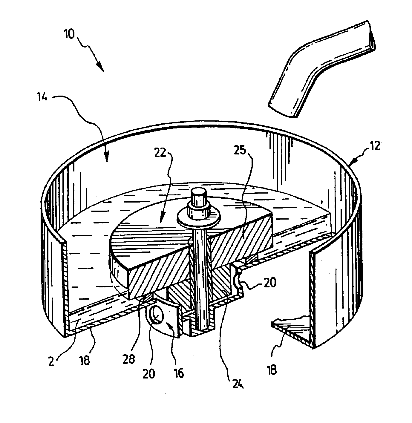
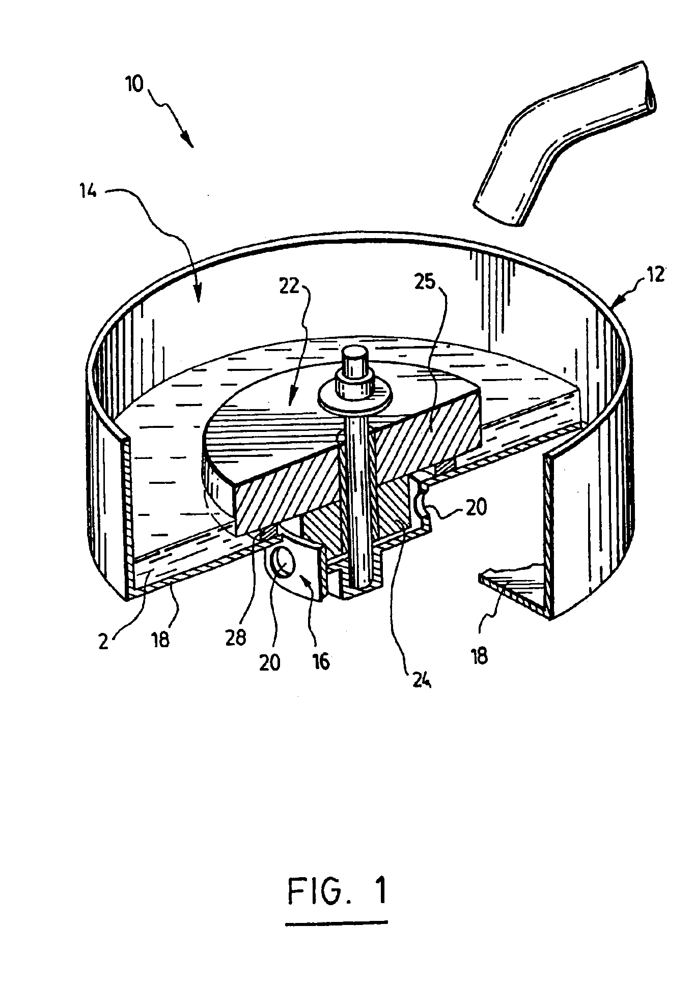
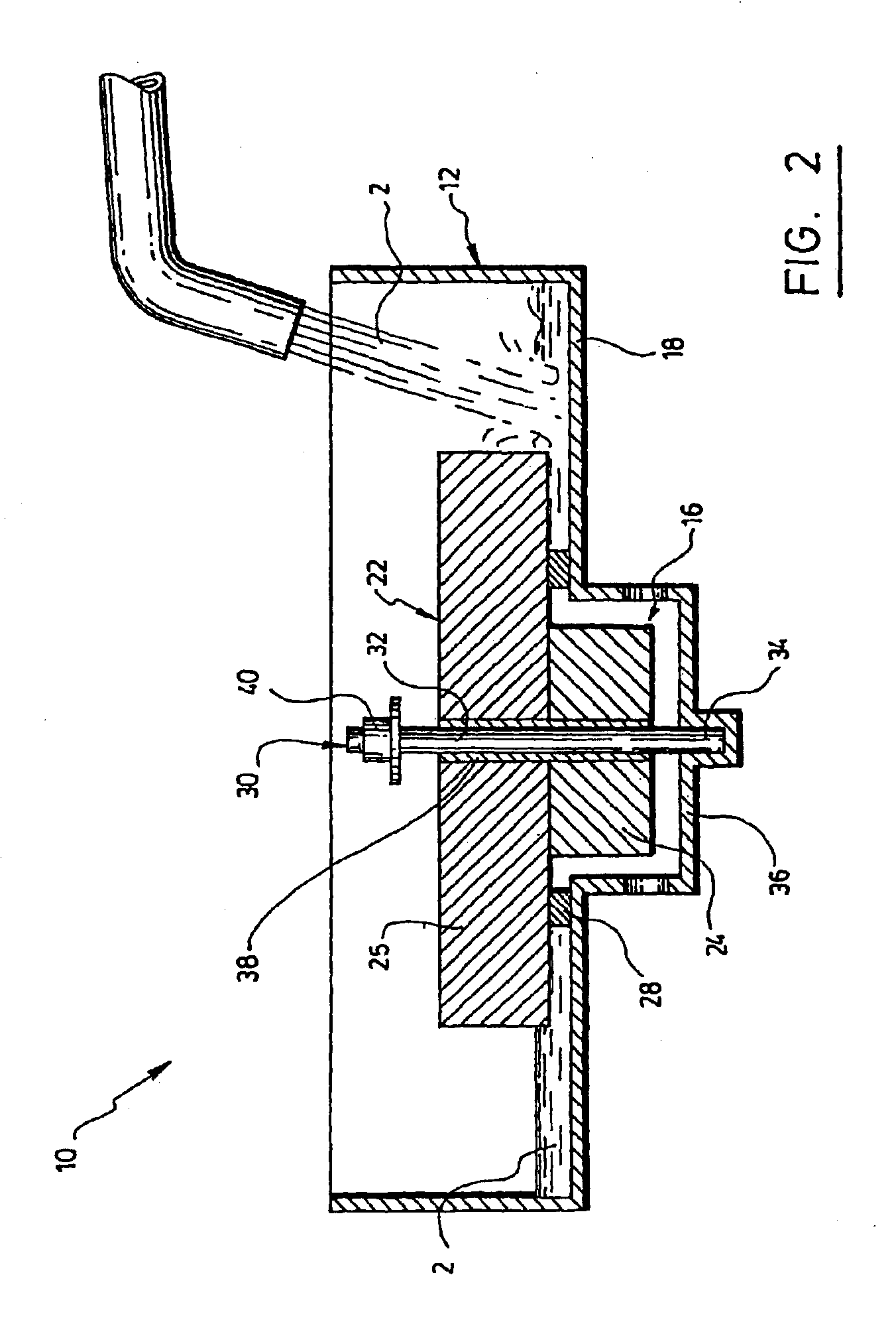
[0041]Referring to FIGS. 1 to 9, the buoyancy flushing apparatus (10) comprises a reservoir (12) for accumulating liquid (2), having an inlet (14) for receiving liquid, which inlet (14) consists, in this case, of the open top of the reservoir (12), and an outlet chamber (16) recessed in a bottom wall (18) of the reservoir (12).

[0042]In order to flush the outlet chamber more rapidly and thereby obtain a more important pulse, the outlet chamber (16) preferably includes more than one outlet (20). This mode of realisation could also be used for flushing liquid in more than one direction. As can be appreciated, the preferred embodiment illustrated comprises four of these outlets (20) evenly distributed around the outlet chamber (16). It is...


PUM


Abstract

A buoyancy flushing apparatus is disclosed which comprises a reservoir for accumulating liquid, having an inlet for receiving liquid and an outlet chamber recessed in a bottom wall of the reservoir. The outlet chamber includes an outlet for draining liquid out of the reservoir. The apparatus further comprises an outlet valve movable between a down position where liquid accumulates in the reservoir and a raised position where liquid accumulated in the reservoir is flushed out via the outlet. The outlet valve comprises a ballast unit sized and shaped to fit loosely in the outlet chamber when said valve is in the down position; and a float unit topping the ballast unit to move the valve in the raised position by buoyancy when a sufficient amount of liquid is accumulated in the reservoir, thereby providing a passageway for liquid between the bottom wall of the reservoir and the valve leading to the outlet in the outlet chamber to flush liquid out of the reservoir. Guiding means are provided for guiding the outlet valve between the down position and the raised position. The apparatus can be used for applications such as water treatment and irrigation. It could advantageously be used for directing and spreading waste water previously treated in a septic tank to different sanitary treating fields.

Description

[0001]This application claims priority from pending Canadian Patent Application No. 2,403,610 filed on Sep. 17, 2002.FIELD OF THE INVENTION[0002]The present invention is concerned with a flushing apparatus and a method thereof. The present invention also relates to an apparatus for flushing and distributing predetermined and adjustable volumes of liquid towards one or several directions or surfaces to be used for applications such as water treatment and irrigation. It could advantageously be used for directing and spreading waste water previously treated in a septic tank, or other treatment units, to different sanitary treating fields.BACKGROUND OF THE INVENTION[0003]Already known in the prior art, there are the flushing or dosing systems involving a hydraulic event used for example in septic fields, or other systems such as irrigation systems. These systems use gravity powers to obtain a fast flow of water. Most often, these prior art flushing systems use a float body which floats ...

Claims


Application Information

Patent Timeline
IPC IPC(8): B65C1/00B65C1/04B65C9/26B65C9/32B65C9/08B65C9/18E03F1/00E02B13/02E02B13/00E03F5/10F16K31/18F16K31/22
CPCE02B13/02F16K31/22E03F5/107E03F1/002E02B2201/50E03F2201/30Y10T137/0324Y10T137/7319Y10T137/7326Y10T137/7323Y10T137/053Y10T137/7426Y10T137/7404Y10T137/7436
Inventor MALENFANT, MARC-ANDREBERUBE, YVESVIEL, NICOLASLACASSE, ROGERDAUTAIS, JEAN-PIERRE
Owner PREMIER TECH EAU & ENVIRONNEMENT LTEE
Why Eureka
Try Eureka