Power output device, hybrid vehicle, and method of controlling them

Inactive Publication Date: 2005-05-03
TOYOTA JIDOSHA KK
View PDF18 Cites 118 Cited by
  • Summary
  • Abstract
  • Description
  • Claims
  • Application Information

AI Technical Summary

Benefits of technology

[0073]The control method of the present invention adequately changes over the connection state of the hybrid vehicle, thus ensuring a drive that takes advantage of the characteristics of both the parallel hybrid vehicle and the series hybrid vehicle. The control method may be applied to the vehicle having any o

Problems solved by technology

The loss in the course of the power transmission may be increased according to the driving conditions of the vehicle and lower t

Method used


Image

  • Power output device, hybrid vehicle, and method of controlling them
  • Power output device, hybrid vehicle, and method of controlling them
  • Power output device, hybrid vehicle, and method of controlling them

Examples


first embodiment

(1) Construction of First Embodiment

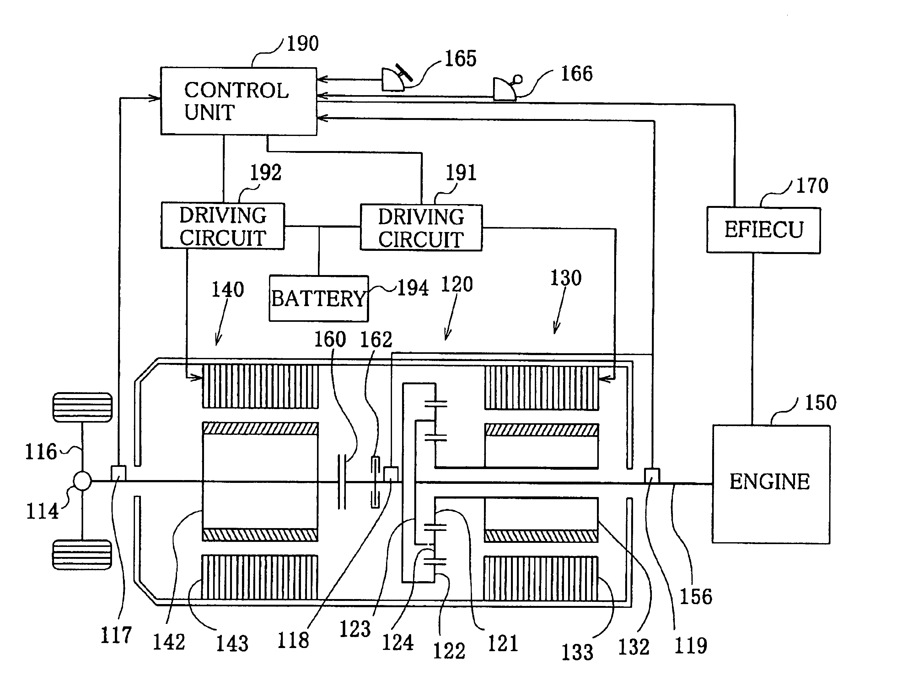
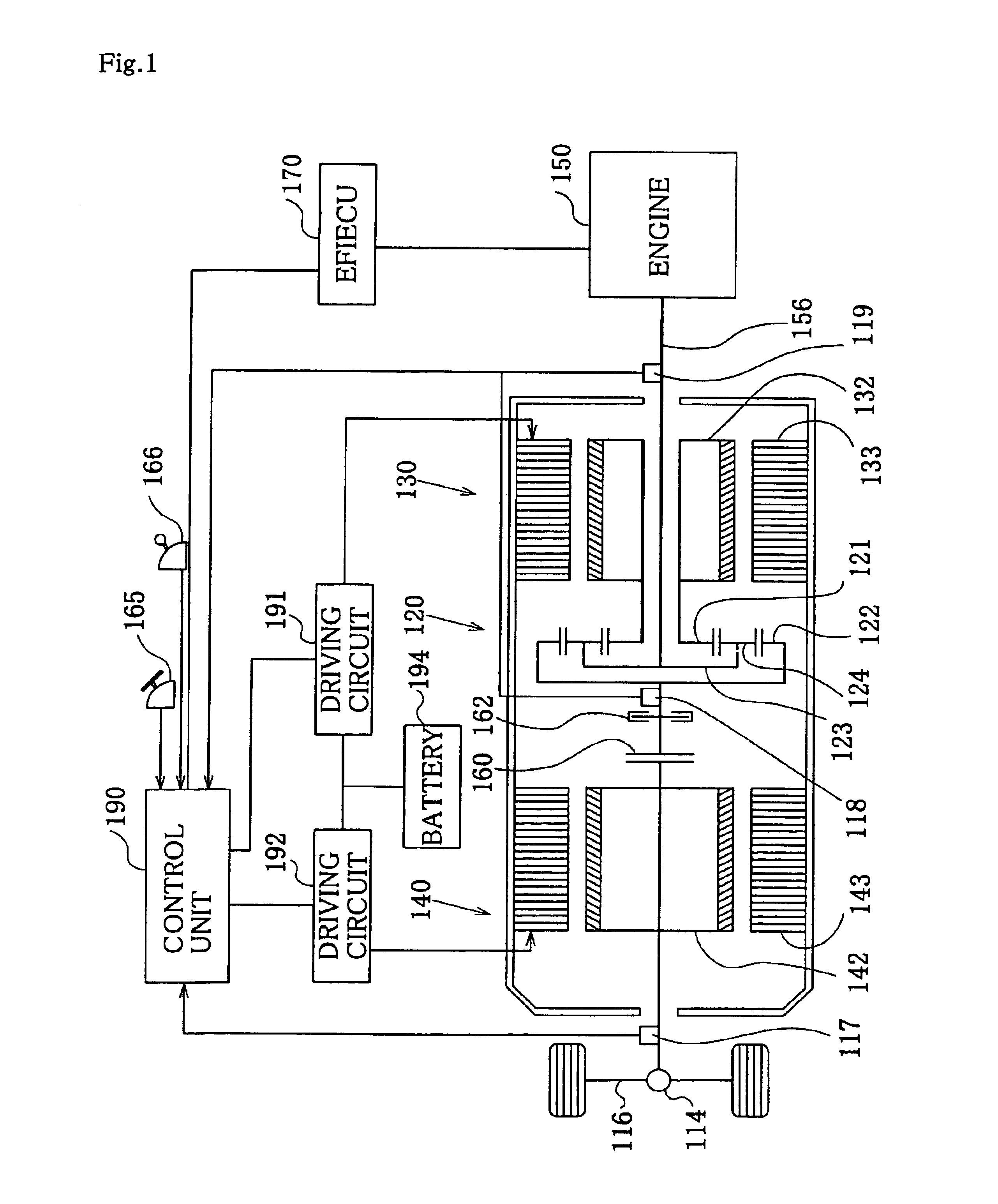
[0113]The construction of a first embodiment is discussed below with reference to FIG. 1. FIG. 1 schematically illustrates the structure of a hybrid vehicle with a power output apparatus of the first embodiment mounted thereon. The hybrid vehicle has a power system of the following construction. An engine 150 included in the power system is a conventional gasoline engine and rotates a crankshaft 156. An EFIECU 170 controls driving of the engine 150 and is constructed as a one-chip microcomputer including a CPU, a ROM, and a RAM. The CPU controls fuel injection of the engine 150 and carries out other control operations according to programs recorded in the ROM. In order to attain such control, a diversity of sensors representing the driving conditions of the engine 150 are connected to the EFIECU 170. Such sensors and switches are omitted from the illustration. The EFIECU 170 electrically connects with a control unit 190 and transmits various piece...

second embodiment

(3) Second Embodiment

[0220]A hybrid vehicle in a second embodiment of the present invention is discussed below. FIG. 18 schematically illustrates the structure of a hybrid vehicle in the second embodiment. In the hybrid vehicle of this embodiment, the power system includes the engine 150, a motor 130B, and another motor 140B that are connected in this order from the upstream side. Like the first embodiment, these three components of the power system are mechanically linked with one another via a planetary gear unit 120A, and a first clutch 160 is disposed between the planetary gear unit 120B and the motor 140B.

[0221]The difference from the first embodiment is that the second embodiment uses a second clutch 161 in place of the brake 162 of the first embodiment. The second clutch 161 connects and disconnects a ring gear 122B with and from a planetary carrier 123B in the planetary gear unit 120B. The control unit 190 controls the connection and disconnection of the second clutch 161. T...

third embodiment

(4) Third Embodiment

[0245]A hybrid vehicle in a third embodiment of the present invention is discussed below. FIG. 22 schematically illustrates the structure of a hybrid vehicle in the third embodiment. In the hybrid vehicle of this embodiment, the power system includes the engine 150, a motor 140C, and another motor 130C that are connected in this order from the upstream side. While there is no motor directly linked with the crankshaft 156 of the engine 150 in the first and the second embodiments, the motor 140C is directly linked with the crankshaft 156 in the third embodiment.

[0246]In the structure of the third embodiment, a planetary carrier 123C in a planetary gear unit 120C connects with the crankshaft 156 of the engine 150, a sun gear 121C connects with the motor 130C, and a ring gear 122C connects with the axle 116. A clutch 160C is provided between the motor 140C and the planetary gear unit 120C. A brake 162C that constrains the rotation of the planetary carrier 123C is dis...


PUM


Abstract

In a planetary gear unit 120, a planetary carrier 123 is linked with an engine 150, a sun gear 121 with a motor 130, and a ring gear 122 with a motor 140 and an axle 116. A clutch 160 is disposed between the planetary gear unit 120 and the motor 140 to connect and disconnect the planetary gear unit 120 with and from the motor 140. A brake 162 is also provided to constrain the ring gear 122 in a released position of the clutch 160. The state of coupling the clutch 160 attains the structure of a parallel hybrid vehicle. The state of releasing the clutch 160 and activating the brake 162 to constrain the ring gear 122 attains the structure of a series hybrid vehicle. The technique of the present invention changes over the drive mode according to the driving state of the hybrid vehicle, thus ensuring an efficient drive that takes advantage of the characteristics of the respective drive modes.

Description

TECHNICAL FIELD[0001]The present invention relates to a power output apparatus that has both an engine and a motor as power source and is capable of changing over the connection state of the motor and the engine, as well as to a hybrid vehicle and a method of controlling the hybrid vehicle.BACKGROUND ART[0002]Hybrid vehicles having both an engine and a motor as power source have been proposed recently. The hybrid vehicles are divided into two large groups: series hybrid vehicles and parallel hybrid vehicles. In the series hybrid vehicle, a generator converts all the output power of the engine into electric power and a motor linked with a drive shaft is driven with the electric power. In the parallel hybrid vehicle, the output power of the engine is divided into two portions. One portion is transmitted directly to the drive shaft in the form of mechanical power, whereas the residual portion is converted into electric power and output to the drive shaft.[0003]The series hybrid vehicle...

Claims


Application Information

Patent Timeline
IPC IPC(8): B60L11/12B60L11/02B60K6/04B60K6/00B60K1/02B60K1/00B60K17/356B60K17/34B60K17/04B60K6/20B60K6/26B60K6/365B60K6/40B60K6/442B60K6/445B60K6/448B60L50/15B60L50/16B60W10/00B60W10/02B60W10/04B60W10/06B60W10/08B60W10/10B60W10/12B60W10/26B60W20/00F02D29/00F02D29/02F02D29/06
CPCB60K6/387B60K6/445B60K6/448B60L11/123B60L11/14B60W10/02B60W10/06B60W10/08B60W10/26B60W20/00B60K6/365B60K1/02Y02T10/6239B60K17/356B60L2220/12B60L2220/14B60L2240/486B60L2240/62B60L2270/145B60W30/18036B60W2540/16B60W2550/402B60W2710/105Y02T10/56Y02T10/6217Y02T10/6243Y02T10/6265Y02T10/6286Y02T10/7077Y02T10/7291Y02T90/16Y02T90/162Y10S903/946Y10S903/91Y10S903/914B60L50/16B60L50/61B60W2556/50Y02T10/40Y02T10/62Y02T10/70Y02T10/7072Y02T10/72Y02T10/84B60W20/20
Inventor HATA, HIROSHIMATSUI, HIDEAKIIBARAKI, RYUJI
Owner TOYOTA JIDOSHA KK
Why Eureka
Try Eureka