Liquid jetting apparatus

a technology of liquid jetting apparatus and insulating conductor, which is applied in the direction of insulated conductors, flat/ribbon cables, cables, etc., can solve the problems of preventing the printing operation from being smoothly performed, affecting the effect of printing operation, and bending of the end of the jetting device, so as to reduce the effect of disturbance attributable to the disturbance relative to the peripheral device, and reduce the incidence of printing failur

Inactive Publication Date: 2005-05-03
SEIKO EPSON CORP
View PDF8 Cites 9 Cited by
  • Summary
  • Abstract
  • Description
  • Claims
  • Application Information

AI Technical Summary

Benefits of technology

[0028]With this arrangement, since the current in each negative conductive patterns is reduced by half, the affect attributable to the mutual inductance between the first and second flexible flat cables can be reduced. Thus, the pressure generating elements that cope with the individual ink types can be operated more normally, shortages of ink for ejection seldom occur, and there is a considerable reduction in the incidence of printing failures.
[0029]When two of the first conduc

Problems solved by technology

However, when a wider flexible flat cable 12′ is continuously bent during printing, it can interfere with associated, peripheral members and prevent the printing operation from being performed smoothly.
Otherwise, if the torsional deformation of a wide flexible flat cable 12′ occurs, its ends may be stretched too far and torn when it is bent during printing.
Accordingly, insuffi

Method used


Image

  • Liquid jetting apparatus
  • Liquid jetting apparatus
  • Liquid jetting apparatus

Examples


first embodiment

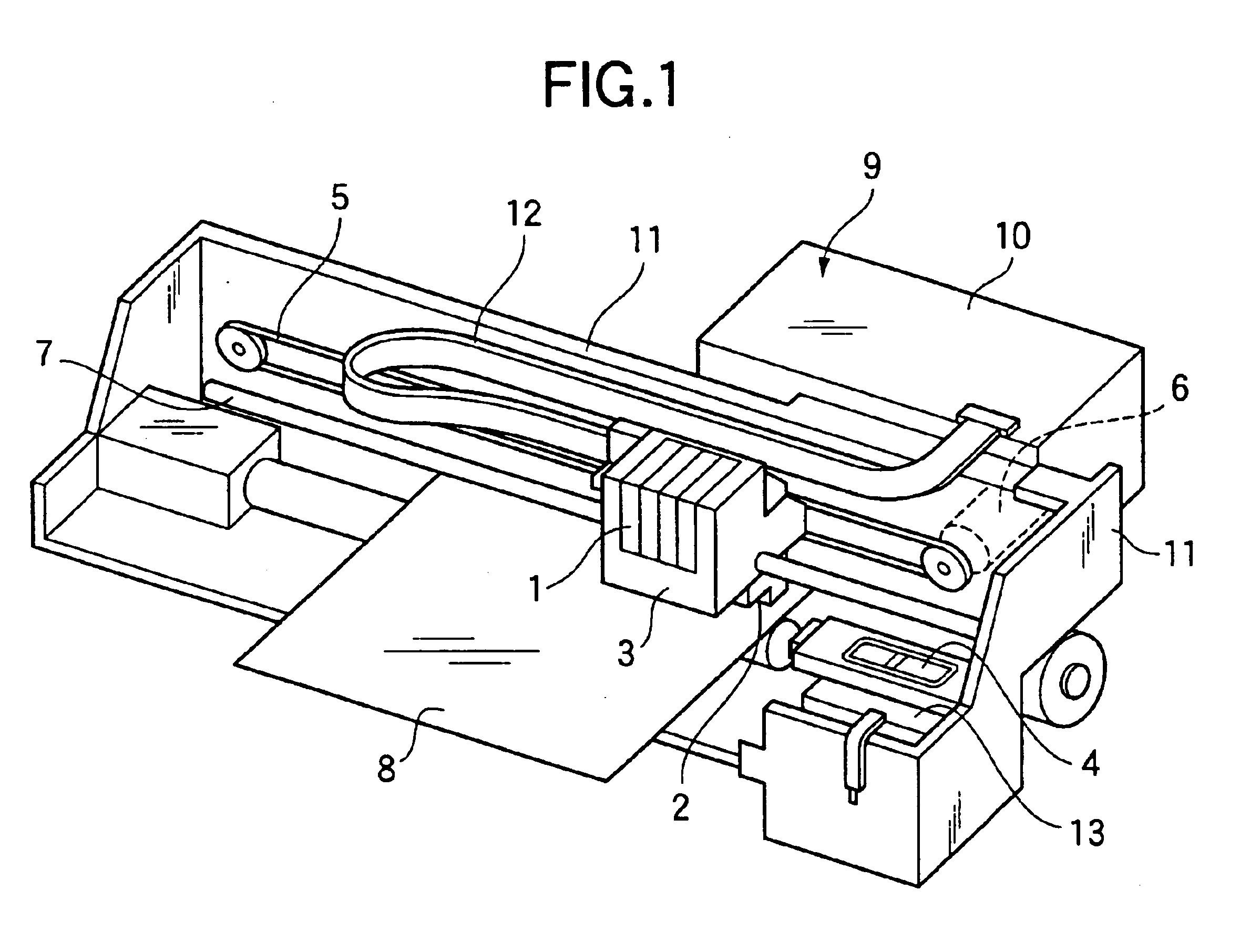
[0067]FIG. 1 shows an ink jet recording apparatus according to the invention. Since this structure is basically the same as that shown in FIG. 17, the same reference numerals are used to denote corresponding components and detailed explanation will be omitted.

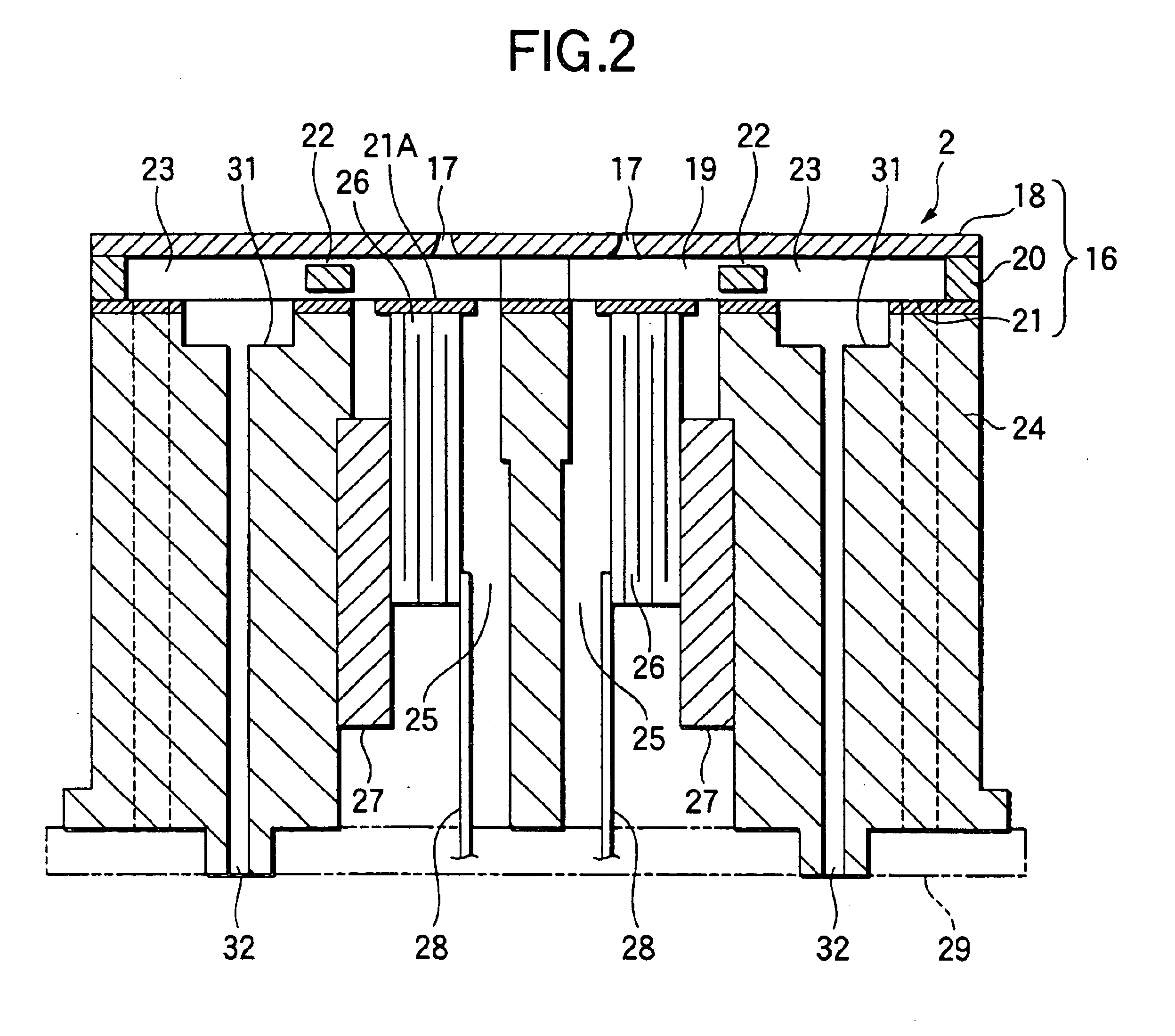
[0068]The recording head 2 will now be explained with reference to FIG. 2. A channel unit 16 is formed by laminating a nozzle plate 18 formed with nozzle orifices 17, a channel forming substrate 20 formed with pressure chambers 19 communicate with the nozzle orifices 17, and a vibration plate 21 for closing the lower openings of the pressure chambers 19. Ink reservoirs 23 which store ink to be introduced into the pressure chambers 19 are formed in the channel forming substrate 20 and communicated with the pressure chambers 19 via ink channels 22.

[0069]A head case 24, which is a principal member of the recording head 3, is formed by the injection molding of a thermosetting resin or a thermoplastic resin. Piezoelectric vibrators ...

third embodiment

[0079] since the current flowing in one positive conductive pattern 14A and one negative conductive pattern 14B is reduced, the magnetic affect attributable to each conductive pattern 14 can be reduced, and the affect attributable to the disturbance relative to a peripheral device can be reduced considerably. The other effects are the same as those obtained in the two embodiments.

fourth embodiment

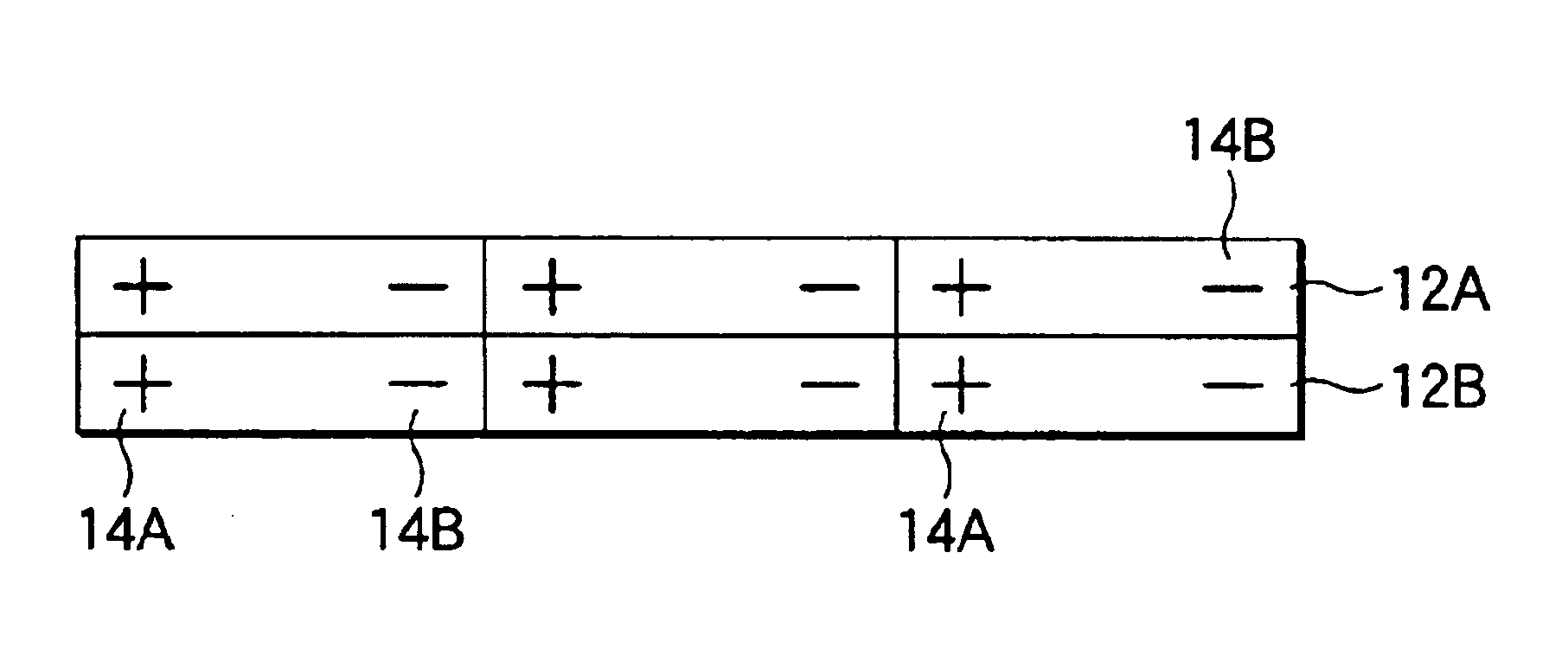
[0080]FIG. 7 shows the invention. In this embodiment, the first flexible flat cable 12A is shifted widthwise relative to the second flexible flat cable 12B a distance equivalent to one conductive pattern, and the positive and negative conductive patterns 14A and 14B of the first flexible flat cable 12A are arranged in an inverted order relative to those of the second flexible flat cable 128. It should be noted that one positive conductive pattern 14A and one negative conductive pattern 14B are provided for each input line. That is, in this example, for the upper, first flexible flat cable 12A, the “positive” conductive patterns 14A and the “negative” conductive patterns 14B are arranged in this order from left to right, while for the lower, second flexible flat cable 12B, the “negative” conductive patterns 14B and the “positive” conductive patterns 14A are arranged in this order from left to right. The remainder of the structure is the same as in the previous embodiments, and the sa...


PUM


Abstract

A flexible flat cable connects a drive circuit and a liquid jetting head to supply a drive signal to pressure generating elements. The flat cable includes a plurality of laminated layers, each provided with a plurality of first conductive patterns each connecting a positive pole of the drive circuit and a positive pole of one of the pressure generating elements, and a plurality of second conductive patterns each connecting a negative pole of the drive circuit and a negative pole of one of the pressure generating elements. Each of at least one of the first conductive patterns provided in one of the laminated layers faces one of the first conductive patterns provided in adjacent one of the laminated layers. Each of at least one of the second conductive patterns provided in one of the laminated layers faces one of the second conductive patterns provided in adjacent one of the laminated layers.

Description

BACKGROUND OF THE INVENTION[0001]The present invention relates to a liquid jetting apparatus such as a recording head for an ink jet recording apparatus, an electrode member ejection head for an electrode forming apparatus, an organic substance jetting head for a bio-chip manufacturing apparatus, or the like, which records images and characters on a recording sheet by ejecting ink droplets from nozzle orifices.[0002]FIG. 17 shows a related-art ink jet recording apparatus, which is one kind of the liquid jetting apparatus, comprising: a carriage 3, wherein an ink cartridge 1 is mounted on the upper face while a recording head 2 is attached to the lower face, and a cap 4 for covering the recording head 2.[0003]The carriage 3 is connected by a timing belt 5 to a stepping motor 6, and reciprocates along a guide bar 7 in the widthwise direction of a recording sheet 8. A drive circuit 9, which is arranged in a case 10 fixed to a wall frame 11, is provided to control the ejection of ink fr...

Claims


Application Information

Patent Timeline
IPC IPC(8): B41J2/14B41J2/045B41J2/05B41J2/055B41J2/01
CPCB41J2/14274B41J2002/14491
Inventor HIRAMOTO, GOKITAKAHASHI, TOMOAKI
Owner SEIKO EPSON CORP
Why Eureka
Try Eureka