Compact wastewater cleaning apparatus

a technology for wastewater and cleaning equipment, applied in the direction of vacuum distillation separation, vessel construction, separation process, etc., can solve the problems of/or prohibit such practices, and achieve the effect of facilitating rapid and clean removal and disposal of waste materials

Inactive Publication Date: 2005-05-03
RAVAN HLDG LLC
View PDF7 Cites 20 Cited by
  • Summary
  • Abstract
  • Description
  • Claims
  • Application Information

AI Technical Summary

Benefits of technology

[0006]Further features of the invention include a special liner in the wastewater receiving vessel of the apparatus to isolate the wastewater from the vessel itself and facilitate rapid and clean removal and disposal of waste material after evaporation of the water, and paired thermally-activate

Problems solved by technology

Whereas in the past it was acceptable merely to dump such waste liquids in the ground or in sewer systems, current good practices and environmental laws and regulations now severely discourage and/or prohibit such practices.
Although very laudable in intent, the result can be v

Method used


Image

  • Compact wastewater cleaning apparatus
  • Compact wastewater cleaning apparatus
  • Compact wastewater cleaning apparatus

Examples


Embodiment Construction

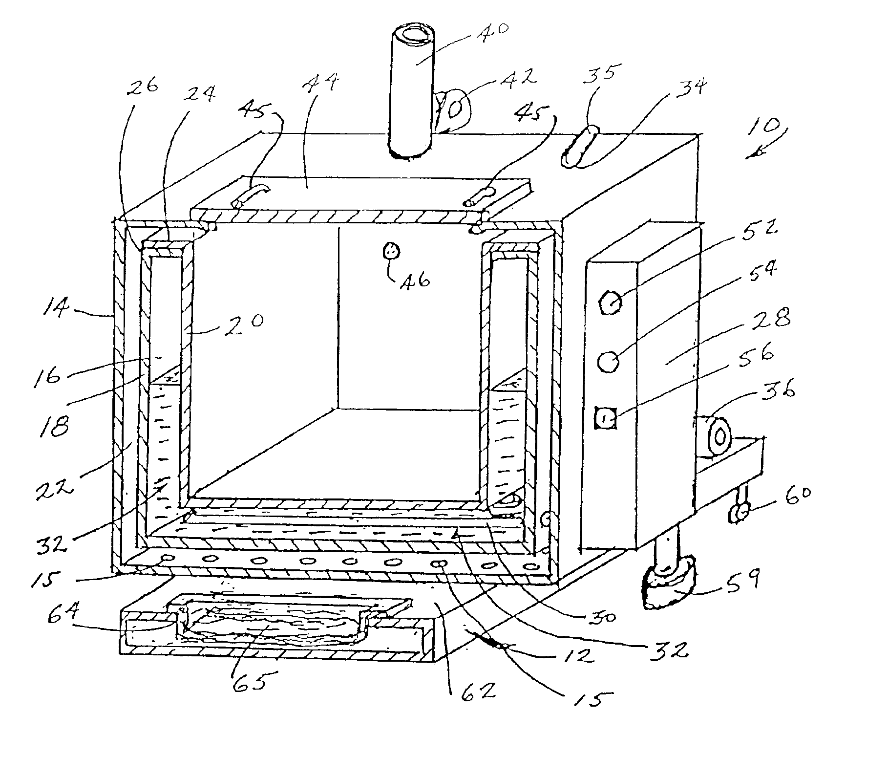
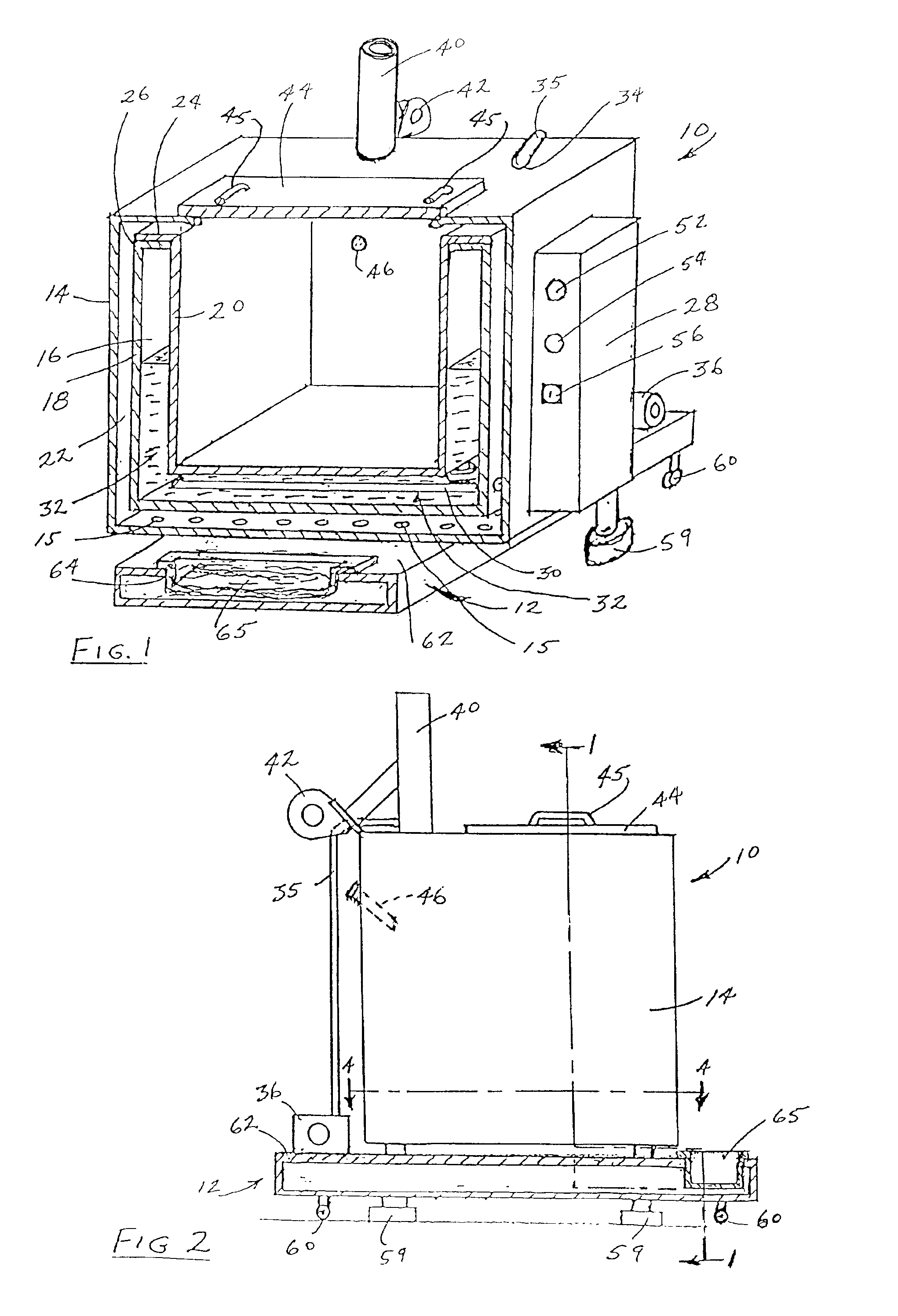
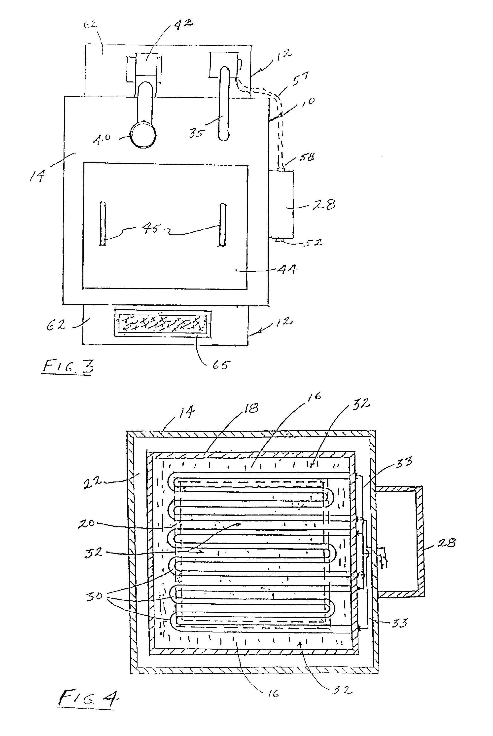
[0016]Referring to FIG. 1, a preferred embodiment of the present invention comprises a wastewater treatment apparatus 10 and an optional separate wastewater receiving tank 12. Apparatus 10 includes an external jacket 14 substantially cubic in shape. Contained inside and spaced from jacket 14 is an interior heat generating chamber 16 (e.g., 4 inches wide at its four sides and 6 inches at its bottom) which is defined at its outside by a heating vessel 18 (e.g., 10 gauge steel) having side walls and a bottom wall as shown, and on the inside by a fluid (e.g., wastewater) receiving vessel 20 preferably of titanium or stainless steel (e.g., about 24 inches in all three dimensions and 15½ gauge). Heating vessel 18 in turn is spaced from outer jacket 14 by an air space 22 (e.g., about 2 inches in width on all four sides and at its top and bottom) to insulate jacket 14. Although not shown, heating vessel 18 may be supported at its bottom by jacket 14 using vertical posts or the like. The bot...


PUM

PropertyMeasurementUnit
Temperatureaaaaaaaaaa
Capacitanceaaaaaaaaaa
Temperatureaaaaaaaaaa

Abstract

A compact, self-contained apparatus for treating wastewater containing as impurities and pollutants various non-volatile (at water boiling points) fluids such as greases, oils and soaps, a vessel for collecting the wastewater, a heating chamber including electric heating elements and a heat transfer liquid such as mineral oil to heat the wastewater admixture to boil off the water and to reduce the volume of liquid for disposal, and a wastewater supply tank positioned under the apparatus. The apparatus may further include a disposable liner to isolate the wastewater from the vessel itself and facilitate rapid and clean removal and disposal of waste material after evaporation of the water, and thermally-activated sensors to maintain a desired temperature differential between the heating elements and the heat transfer liquid contained in the apparatus.

Description

PRIOR APPLICATIONS[0001]This application is based on and claims the benefit of the filing dates of U.S. Provisional Patent Applications Ser. No. 60 / 147,736, filed Aug. 6, 1999, and Ser. No. 60 / 159,664, filed Oct. 15, 1999, both entitled Compact Wastewater Cleaning Apparatus (“the co-pending provisional applications”), the entire disclosures of which are incorporated by reference into this application.FIELD OF INVENTION[0002]This application relates to apparatus for the treatment of wastewater resulting from cleaning of, for example, buildings, vehicles and machinery by reducing the volume of wastewater required for disposal by an efficient water evaporation.BACKGROUND OF INVENTION[0003]As explained in my U.S. Pat. No. 5,582,680, and in my U.S. Pat. No. 6,200,428, filed Mar. 31, 1998, the entire disclosures of which are incorporated by reference into this application, good manufacturing processes, concern for the environment, and changes in environmental practices and regulations all...

Claims


Application Information

Patent Timeline
IPC IPC(8): B01D1/30B01D1/00C02F1/04
CPCB01D1/0017B01D1/0052B01D1/30C02F1/048Y10S159/41Y10S159/15Y10S203/11
Inventor VANKOUWENBERG, RAYMOND E.
Owner RAVAN HLDG LLC
Why Eureka
Try Eureka