Spinning disk evaporator

a technology of spinning disk and evaporator, which is applied in the direction of evaporation, lighting and heating apparatus, and separation processes, etc., can solve the problems of inconvenient operation of ultrasonic evaporators, inability to operate for a few hours, and inherently conflicting evaporation steps with final condensation steps, etc., to improve the productivity of evaporators, increase continuous operation time, and increase the range of organic liquids

Inactive Publication Date: 2005-05-03
3M INNOVATIVE PROPERTIES CO
View PDF36 Cites 9 Cited by
  • Summary
  • Abstract
  • Description
  • Claims
  • Application Information

AI Technical Summary

Benefits of technology

[0018]It is an object of this invention to provide an apparatus and method that increases the range of organic liquids which can be employed in a single evaporator.
[0019]It is another object of this invention to provide an apparatus and method that improves the productivity of evaporators by increasing continuous operational time and decreasing maintenance requirements.
[0020]It is a further object of this invention to provide an apparatus and method that provides a larger and more constant material flow rate relative to existing evaporators and that provides for uniform vapor deposition on the target substrate.
[0021]It is a further object of this invention to provide an apparatus and method which eliminates the pulsation in flow and pressure that occur with prior art evaporators.
[0022]It is a further object of this invention to provide an apparatus and method which increases the size of the liquid molecules that can be evaporated without cracking the chemical bonds of the molecule.
[0023]It is a further object of this invention to enhance the ability to condense smaller molecules as compared to prior art evaporators.

Problems solved by technology

The evaporation step, however, is in inherent conflict with the final condensation step.
Problems occur, however, when the ultrasonic evaporation process is attempted in low pressure environments.
Under low pressure environments, ultrasonic evaporators can only be operated a few hours before cleaning the polymerized liquid is required.
Because this is an inherent consequence of the ultrasonic evaporator design, ultrasonic evaporators can only be operated in higher pressure environments, rendering them unsuitable for low pressure vapor formation.
During operation, this system rapidly degenerates and requires frequent cleaning.
Both conventional spinning disk and ultrasonic evaporators have disadvantages which inhibit their effective use for evaporation of organic material in low pressure environments.
Complications arise, however, due to the low pressure in the evaporator which produces low pressure in the feed tube.
This solution, however, does not completely eliminate the existence of low pressure in the capillary tubing.
Additionally, because ultrasonic and conventional spinning disk evaporators have a common dependence on capillary action to deliver the requisite liquid to the evaporator apparatus, the viscosity of the liquid being evaporated is limited to that of a liquid having a viscosity less than 100 cps.
The increased pressure raises the shear stress on the liquid thereby initiating polymerization in the capillary tubing and, consequently, rapidly leading to clogging of the tubing.
Heating, however, makes the liquid susceptible to polymerization and, therefore, could also result in clogging.
Finally, because of the rapid build-up of polymerized or degraded organic material, both ultrasonic and conventional spinning disk devices have short operation times. Short operational times are inefficient and adversely impact productivity.

Method used


Image

  • Spinning disk evaporator
  • Spinning disk evaporator
  • Spinning disk evaporator

Examples


Embodiment Construction

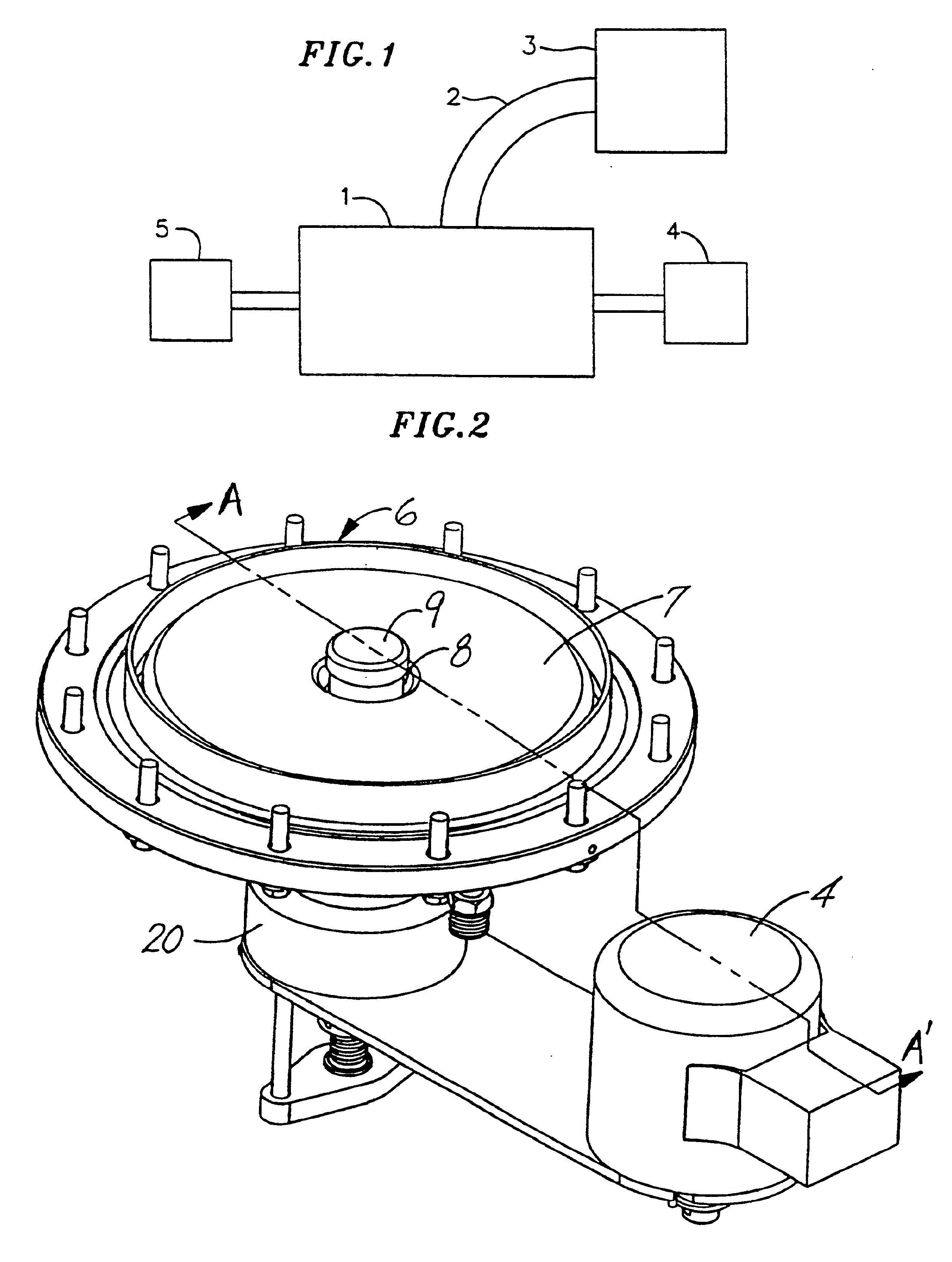
[0030]Referring to the drawings, FIG. 1 illustrates an organic liquid evaporation and condensation apparatus. An evaporation chamber 1 that contains an evaporation apparatus [not shown] is connected by a duct 2 to a condensation chamber 3. A motor 4 which drives the evaporation apparatus and a liquid delivery system 5 capable of controllably delivering liquid to the evaporation apparatus are also attached to the evaporation apparatus. The relative placement of each component in FIG. 1 has been provided for illustration purposes and is not intended to limit the present invention to the illustrated configurations.

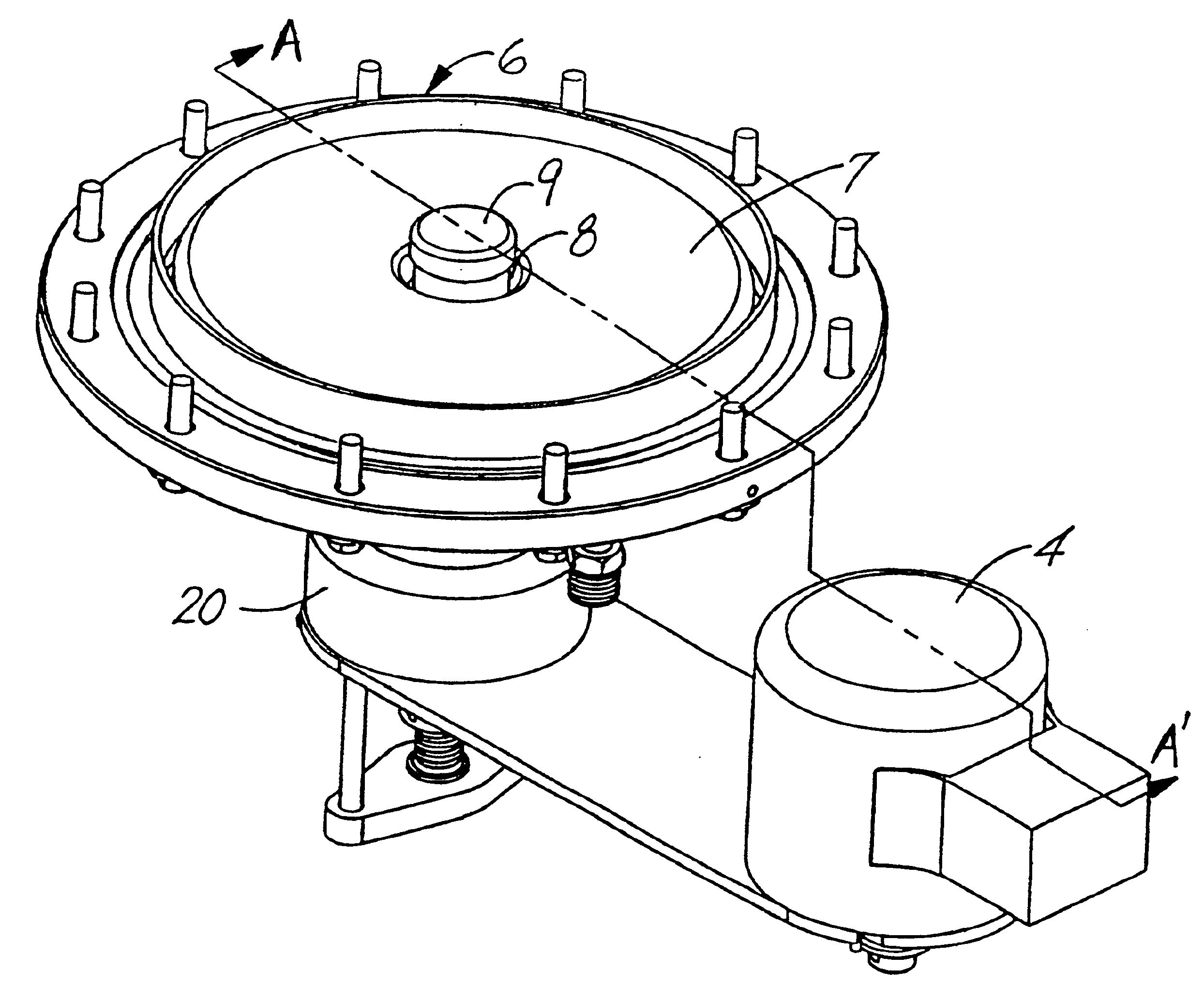
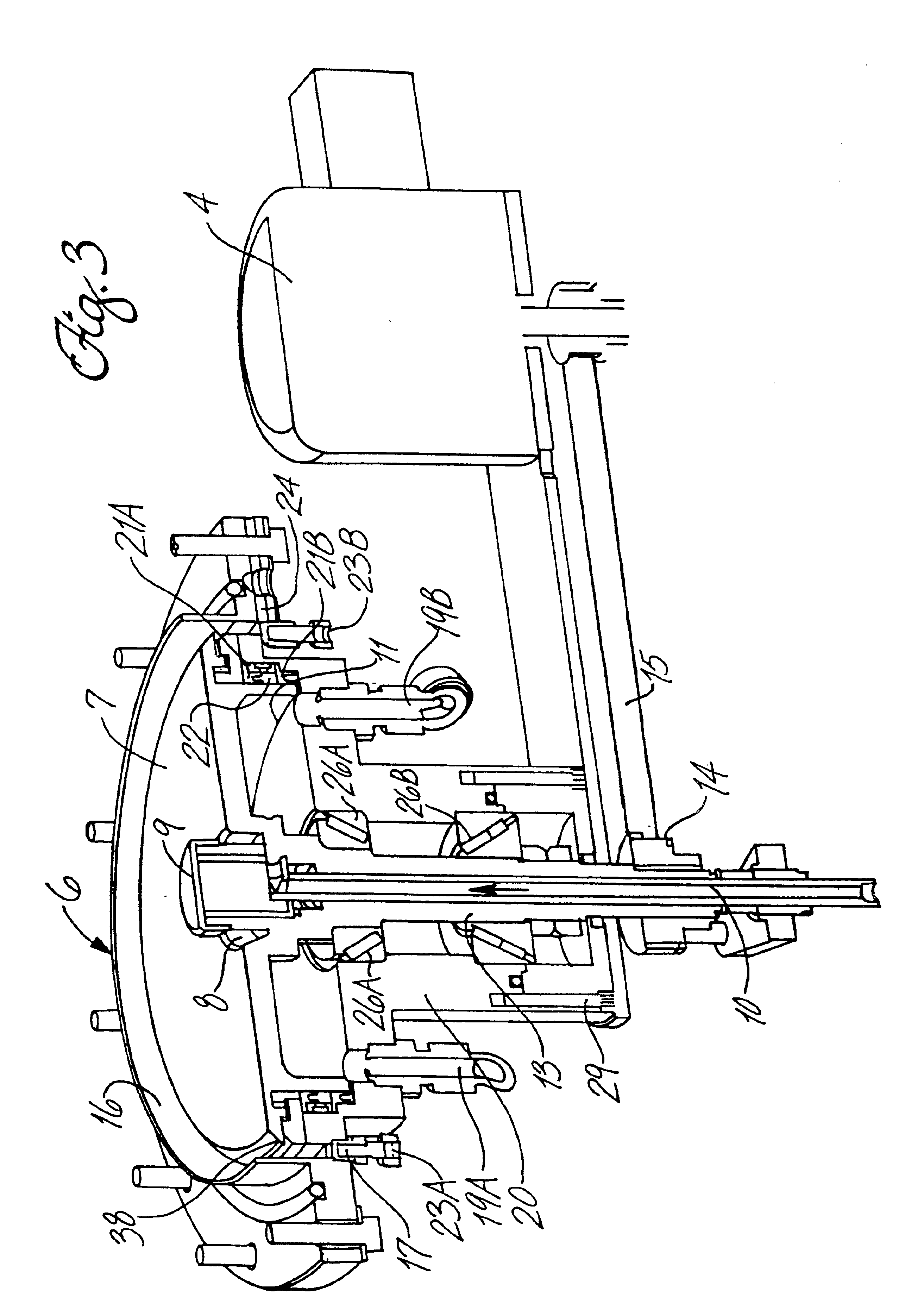
[0031]As shown in FIG. 2, and more specifically in FIG. 3, the evaporation apparatus 6, contained in evaporation chamber 1, is comprised of a substantially horizontally disposed surface 7 with a depression 8 central to the surface 7 structure, which depression is capable of acting as a receptacle for liquid material. Disposed proximate to the depression 8 is a liquid outlet 9...


PUM

PropertyMeasurementUnit
angleaaaaaaaaaa
diameteraaaaaaaaaa
inner diameteraaaaaaaaaa

Abstract

Liquid organic material is controllably delivered to a receptacle located in the center of a heated surface capable of horizontally rotating about its central axis. As the heated surface rotates, material deposited within the central receptacle is forced outwardly and across the rotating surface. As the material moves radially, it evaporates into a vapor which is then transported to one or more nozzles. From the nozzles, the vapor is applied to a substrate and condensed. Relative to existing devices and methods, the present invention enables the evaporation of a wider variety of organic liquids, greater reliability in continuous operation, a decrease in maintenance, and a larger and more constant material flow rate.

Description

CROSS REFERENCE TO RELATED APPLICATIONS[0001]This application is a continuation of U.S. Ser. No. 09 / 007,589, filed Jan. 15, 1998, now U.S. Pat. No. 6,309,508, issued Oct. 30, 2001.FIELD OF THE INVENTION[0002]The present invention relates to an apparatus and a method for the improved evaporation of organic liquids for vapor deposition onto substrates in vacuum environments. Relative to existing devices and methods, the present invention enables the evaporation of a wider variety of organic liquids, greater reliability in continuous operation, a decrease in maintenance, and a larger and more constant material flow rate.BACKGROUND AND OBJECTS OF THE INVENTION[0003]Numerous industries utilize evaporation-vapor deposition systems to coat substrates with desired materials. Illustrative of such applications are U.S. Pat. Nos. 4,290,384, 4,842,893, 4,490,774, 4,325,986, and 4,543,275. Specifically, organic compounds are utilized as coatings in applications as diverse as protective materials...

Claims


Application Information

Patent Timeline
Patent Type & Authority Patents(United States)
IPC IPC(8): C23C16/448B05B17/06B01D1/22B05C11/10
CPCC23C16/4485B05B7/0075
Inventor LEMME, CHARLES DANIELLANGLOIS, MARC G.
Owner 3M INNOVATIVE PROPERTIES CO
Why Eureka
Try Eureka