Optical film, and lighting device and image viewing display using the same

a technology of optical film and lighting device, applied in the field of optical film, can solve the problems of reducing the quantity of light usable for a liquid crystal picture display etc., and the picture displayed becomes dark, and achieves the effect of satisfactory excellent visibility

Inactive Publication Date: 2005-05-03
NITTO DENKO CORP
View PDF2 Cites 11 Cited by
  • Summary
  • Abstract
  • Description
  • Claims
  • Application Information

AI Technical Summary

Benefits of technology

[0009]The present invention aims at providing an optical film that is obtained by applying a retardation layer to a cholesteric liquid crystal layer, that can be used as a brightness enhancement film, and further that provides an excellent visibility satisfactory also when observed not only from a front direction but from an oblique direction in image viewing displays, such as liquid crystal displays. Furthermore, the present invention aims at providing a lighting device and an image viewing displays, such as liquid crystal displays, using the optical film concerned.
[0018]In the above-mentioned optical film of the present invention, a circular polarized light separating layer formed with a cholesteric liquid crystal layer (1) having the above-mentioned virtual thickness direction retardation: RZch, and a retardation layer (2) having the above-mentioned thickness direction retardation: RZre are combined and laminated so that a relationship of RZre / (−RZch)=0.05 through 0.35 may be satisfied. When optical films being combined so that a value of RZre / (−RZch) may be in the range are applied to a brightness enhancement film, a relationship of retardation values improves. As a result, satisfactory visibility may be demonstrated, even when a cholesteric liquid crystal layer (1) is applied to a brightness enhancement film and an image viewing displays, such as a liquid crystal display, are observed not only from front direction but from oblique direction. The above-mentioned value of RZre / (−RZch) is more preferably 0.08 through 0.3, and still more preferably 0.1 through 0.25.
[0024]It is preferable that the absorbing polarizing film (4) is laminated so that the optical axis of the retardation layer (3) and the transmission axis of the absorbing polarizing film (4) intersect at an angle of 35 through 55° in order to improve the above-mentioned visibility. The above-mentioned angle is more preferably 40 through 50°, and still more preferably 43 through 47°.

Problems solved by technology

This means that although influenced with the characteristics of the polarizer used, about 50 percent of light is absorbed by the polarizer, the quantity of the light usable for a liquid crystal picture display etc. decreases so much, and a resulting picture displayed becomes dark.

Method used


Image

  • Optical film, and lighting device and image viewing display using the same
  • Optical film, and lighting device and image viewing display using the same
  • Optical film, and lighting device and image viewing display using the same

Examples


manufacturing example 1

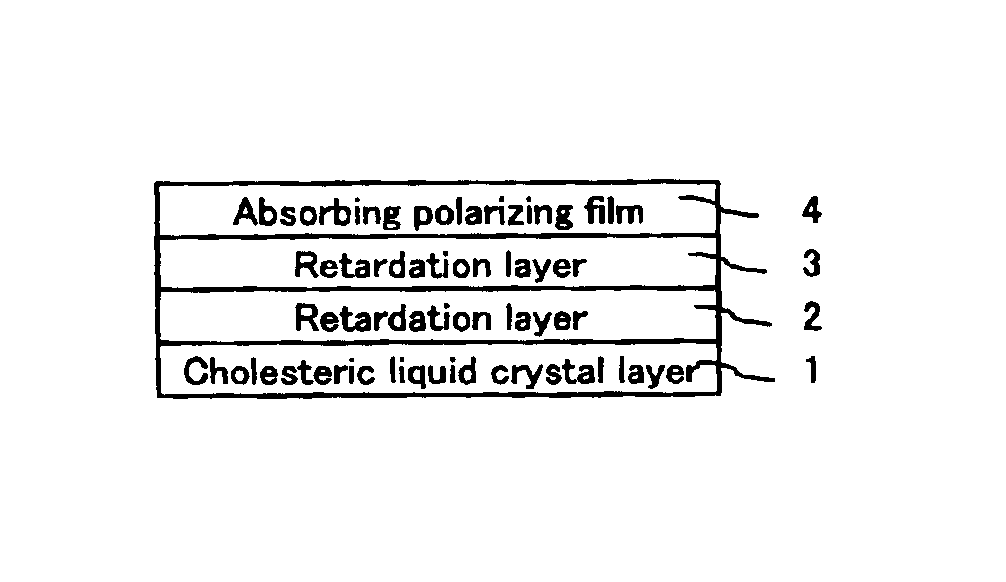
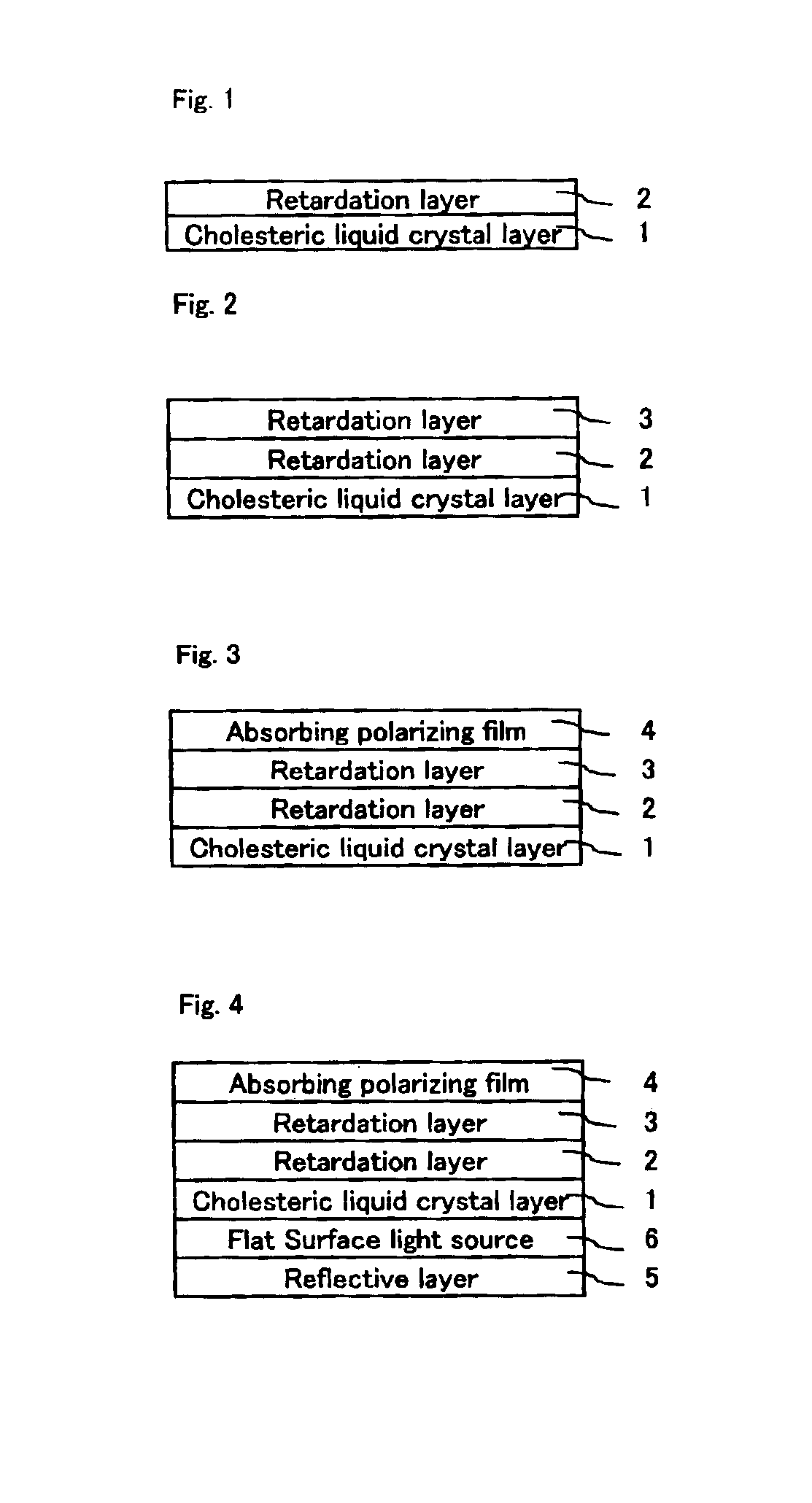
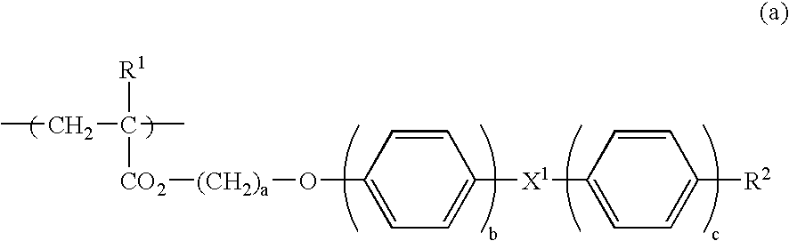
[0110]An oriented film of polyvinyl alcohol having a thickness of 0.1 μm was formed on a triacetylcellulose (TAC) film having a thickness of 50 μm, and rubbing treatment was given. After three layers having 700 nm, 550 nm, and 400 nm of central wavelengths of selective reflection, respectively, were sequentially formed on the oriented film, using an acryl based cholesteric liquid crystal polymer with side chain, then oriented, and finally the layers obtained was changed into a thin film. A thickness of each layer showed 3 μm. As the cholesteric liquid crystal polymer of acryl based with side chain, a polymer having repeating unit represented by a following general formula (1), and having a temperature showing liquid crystal property of 90 through 200° C. (glass transition temperature: 90° C.) was used.

[0111]Formation of the cholesteric liquid crystal layer was carried out in a method that the above-mentioned cholesteric liquid crystal polymer diluted with a solvent by about 25% by ...

manufacturing example 2

[0112]In the manufacturing example 1, except having used a polymer having a repeating unit represented by a following general formula (2) as a cholesteric liquid crystal polymer, a similar method as the manufacturing example 1 was repeated, and a cholesteric liquid crystal layer B having a thickness of Dch (nm) was formed.

The cholesteric liquid crystal layer B showed {(ne−no) / 2}=0.20.

manufacturing example 3

[0113]In the manufacturing example 1, Except having used a polymer having repeating unit represented by a following general formula (3) as a cholesteric liquid crystal polymer, a similar method as the manufacturing example 1 was repeated, and a cholesteric liquid crystal layer C having a thickness of Dch (nm) was formed.

The cholesteric liquid crystal layer C showed {(ne−no) / 2}=0.25.

(Formation of Retardation Layer (2))


PUM

PropertyMeasurementUnit
angleaaaaaaaaaa
thickness Dchaaaaaaaaaa

Abstract

An optical film in which at least one layer of a cholesteric liquid crystal layer (1) and a retardation layer (2) are laminated, wherein an in-plane retardation of the retardation layer (2): (nx1−ny1)×Dre is 5 nm or less, and a virtual thickness direction retardation: RZch, and a thickness direction retardation: RZre have a relationship of RZre / (−RZch)=0.05 through 0.35, can be used as a brightness enhancement film, and further that provides an excellent visibility satisfactory also when observed not only from a front direction but from an oblique direction in image viewing displays, such as liquid crystal displays.

Description

BACKGROUND OF THE INVENTION[0001]1. Field of the Invention[0002]The present invention relates to an optical film. Optical films are used as a brightness enhancement film, and they are further used in combination with other films. Specifically, the present invention relates to a lighting device using the optical film concerned. Furthermore, it relates to an image viewing display in which optical films and the lighting devices are applied, such as a liquid crystal display, an organic electro luminescence display, and a PDP.[0003]2. Description of the Prior Art[0004]The polarizing plate with which a polarizing plate and a brightness enhancement film are adhered together is usually used being prepared in a backside of a liquid crystal cell. A brightness enhancement film shows a characteristic that reflects linearly polarized light with a predetermined polarization axis, or circularly polarized light with a predetermined direction, and that transmits other light, when natural light by ba...

Claims


Application Information

Patent Timeline
Patent Type & Authority Patents(United States)
IPC IPC(8): G02F1/1335G02F1/13G02B5/30G02F1/13357G02F1/13363
CPCG02F1/13362G02F1/13363G02F2413/12G02F2413/02G02F2413/07G02F2001/133543G02F1/133543G02F1/1335
Inventor KAWAMOTO, IKUOSHUTO, SHUNSUKENAKANISHI, SADAHIRO
Owner NITTO DENKO CORP
Why Eureka
Try Eureka