Method and apparatus for filtering an optical beam

a filtering method and optical beam technology, applied in multiplex communication, semiconductor lasers, instruments, etc., can solve the problems of small tuning range of 3 nm, inability of dfb laser transmitters to assign arbitrary channels, and small tuning range of dfb lasers, etc., to achieve precise tuning and compact form factor

Inactive Publication Date: 2005-05-03
INTEL CORP
View PDF150 Cites 55 Cited by
  • Summary
  • Abstract
  • Description
  • Claims
  • Application Information

AI Technical Summary

Benefits of technology

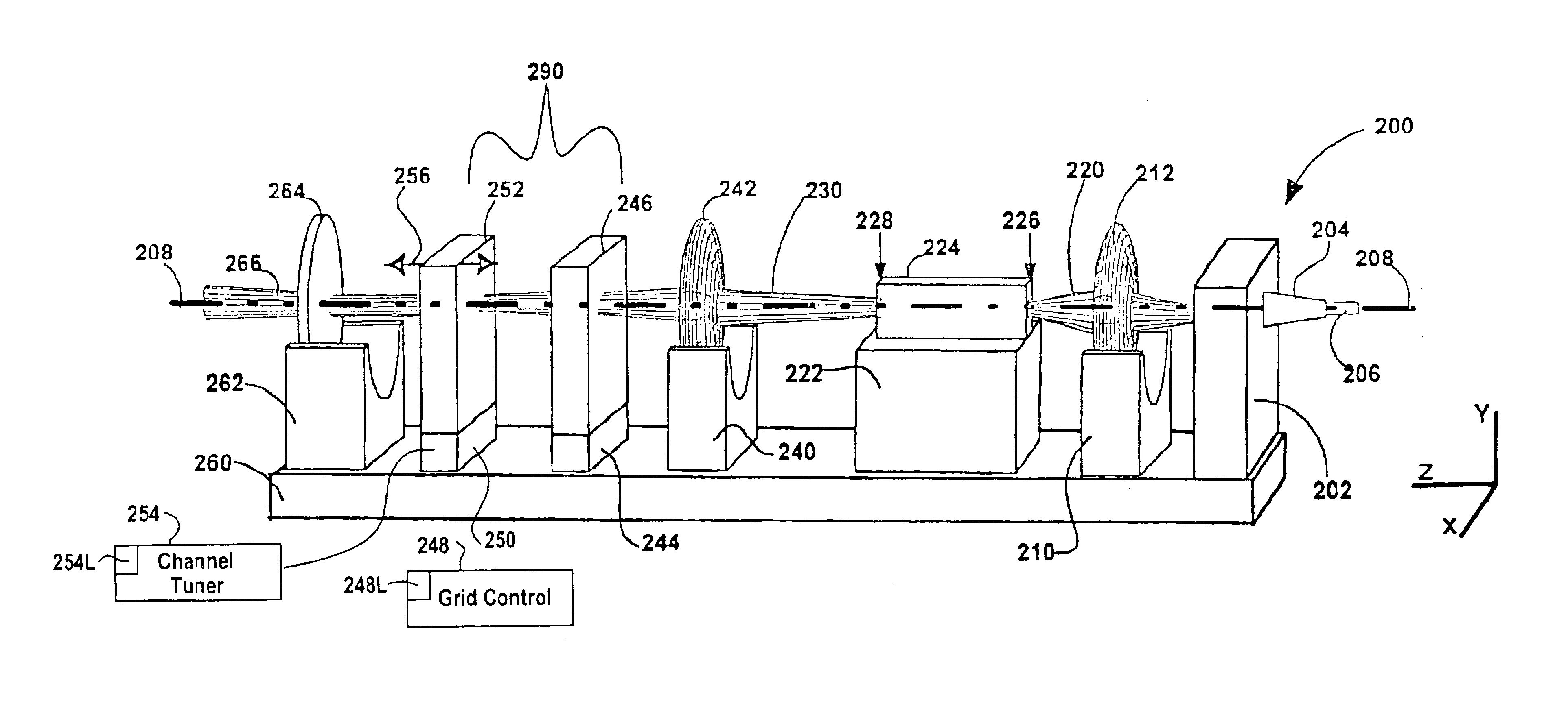
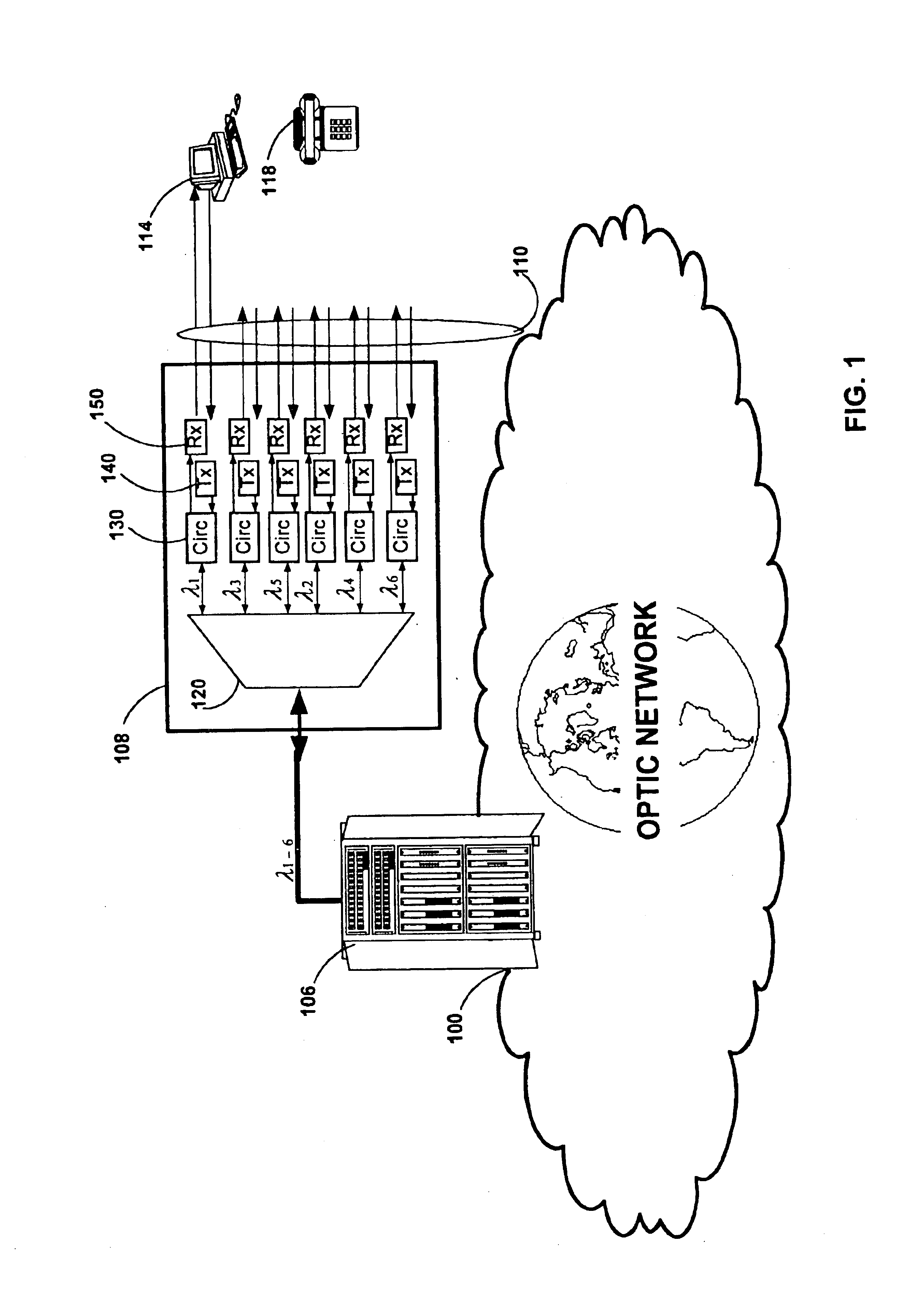
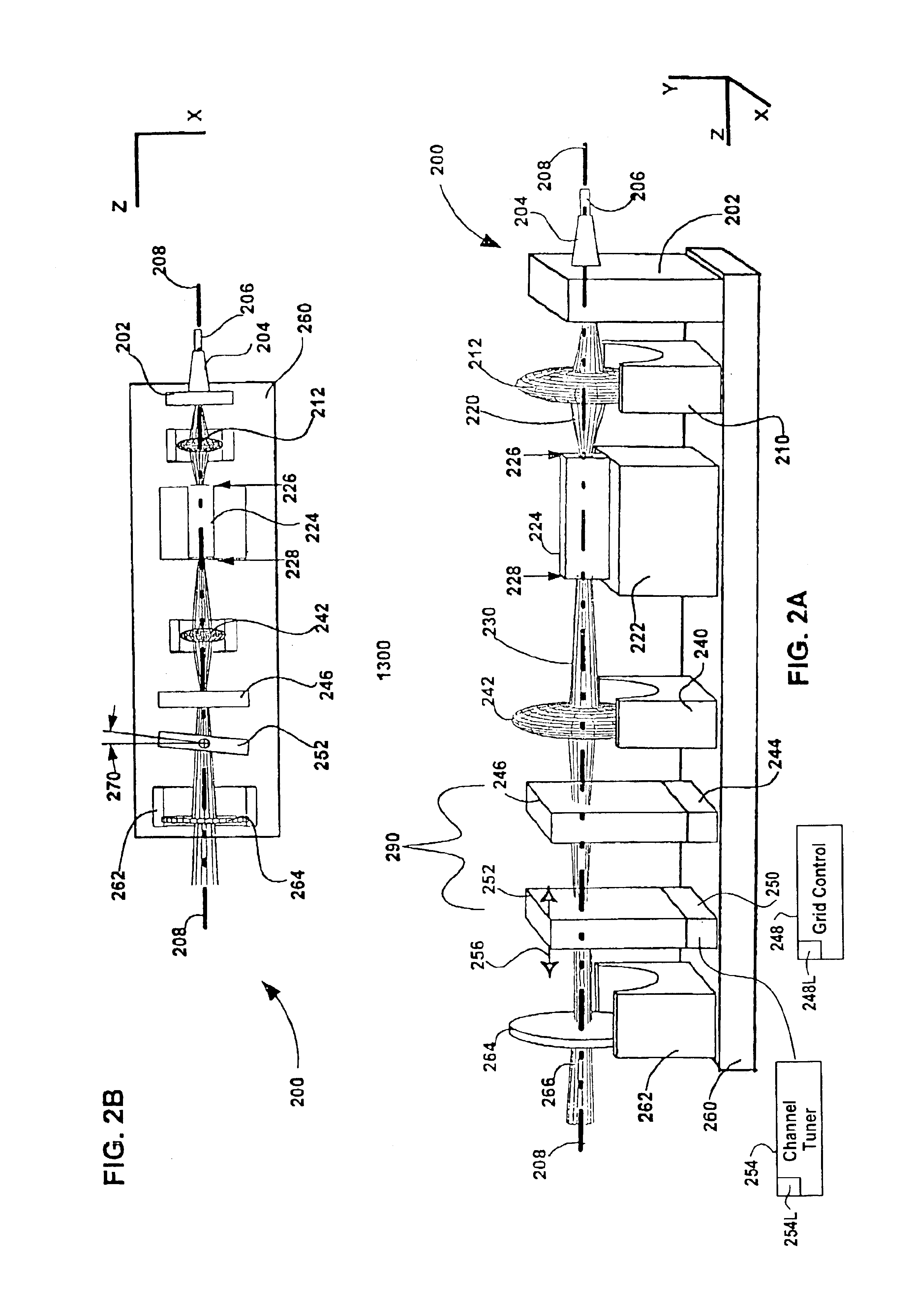
[0012]The invention pertains to wavelength-agile optical filters suitable for wavelength-division-multiplexed (WDM) optical communications networks. More particularly, the invention pertains to optical filters with a wavelength reference that can be remotely switched to arbitrarily selectable channels on a standard grid, and to re-configurable optical communications networks employing same. The present invention provides a communication apparatus with a tunable filter which may be used in a wide range of applications including tuning an external cavity laser (ECL), selecting a wavelength for an add / drop multiplexer and providing channel selection and feedback for a wavelength locker. The filter may be utilized as a discrete component or in combination with circulators, wavelength lockers and gain medium. The filter may be implemented in whole or in part as part of a gain medium. The tunable filter exhibits a compact form factor and precise tuning to any selected wavelength of a predetermined set of wavelengths comprising a wavelength grid. The tunable filter may thus be utilized in telecom applications to generate the center wavelengths for any channel on the ITU or other optical grid.

Problems solved by technology

DFB lasers suffer from the drawback that they have small tuning ranges of ˜3 nm (See, e.g., J. Carroll, J. Whiteaway, & D. Plumb, Distributed feedback semiconductor lasers, SPIE Press, 1998).
As a result, DFB laser transmitters cannot be assigned to arbitrary channels.

Method used


Image

  • Method and apparatus for filtering an optical beam
  • Method and apparatus for filtering an optical beam
  • Method and apparatus for filtering an optical beam

Examples


example

[0070]From a default configuration, where the laser frequency is selected at the wavelength of overlap between the two etalons, the laser can be tuned. As the temperature of the second etalon is changed, it's free-spectral range will change. Given enough change in FSR2, the overlap wavelength will “snap” by FSR1, and a new laser frequency will be selected. One can select FSR1=50 GHz, for example, which corresponds to approximately 2 mm of BK7 glass.

[0071]The following example shows how to determine the required optical path length change (e.g. a combination of thermal expansion and temperature dependent index change) to achieve a single channel snap. Assuming a channel spacing of 50 GHz and that the grid generator is 1.999 mm of BK7, with a FSRGridGen=50 GHz. If the Finesse is 200, the transmission 1 / e2 half-width is ω0=FSR / F=0.25 GHz, and for simplicity, we can choose FSRChannelSel=50.25 GHz. The thickness of the channel selector etalon is therefore 1.989 mm. The wavelengths of int...


PUM


Abstract

The invention pertains to wavelength-agile optical filters suitable for wavelength-division-multiplexed (WDM) optical communications networks. More particularly, the invention pertains to optical filters with a wavelength reference that can be remotely switched to arbitrarily selectable channels on a standard grid, and to re-configurable optical communications networks employing same. The present invention provides a communication apparatus with a tunable filter which may be used in a wide range of applications including tuning an external cavity laser (ECL), selecting a wavelength for an add / drop multiplexer and providing channel selection and feedback for a wavelength locker. The filter may be utilized as a discrete component or in combination with circulators, wavelength lockers and gain medium. The filter may be implemented in whole or in part as part of a gain medium. The tunable filter exhibits a compact form factor and precise tuning to any selected wavelength of a predetermined set of wavelengths comprising a wavelength grid. The tunable filter may thus be utilized in telecom applications to generate the center wavelengths for any channel on the ITU or other optical grid.

Description

CROSS REFERENCE TO RELATED APPLICATIONS[0001]The application is continuation of U.S. application Ser. No. 09 / 626,526 filed Jul. 27, 2000, pending, which claims benefit of U.S. Provisional Application No. 60 / 145,831 filed on Jul. 27, 1999, all of which are hereby incorporated by reference thereto, in their entireties, and to which this application claims priority under 35 U.S.C. Section 120.BACKGROUND OF THE INVENTION[0002]1. Field of Invention[0003]The invention pertains to wavelength-agile optical filters suitable for wavelength-division-multiplexed (WDM) optical communications networks. More particularly, the invention pertains to optical filters with a wavelength reference that can be remotely switched to arbitrarily selectable channels on a standard grid, and to re-configurable optical communications networks employing same.[0004]2. Description of the Related Art[0005]The telecommunications network serving the United States and the rest of the world is presently evolving from an...

Claims


Application Information

Patent Timeline
Patent Type & Authority Patents(United States)
IPC IPC(8): G02B26/00G02B5/28G02B6/34G02B7/00H01S5/00H01S5/14H04J14/02H01S5/0687H01S5/022
CPCG02B5/281G02B5/284G02B6/29358G02B6/29361G02B6/29395G02B26/002H01S5/141G02B26/007H04J14/02H01S3/1062H01S5/02248H01S5/02284H01S5/0687H01S5/02251H01S5/02325
Inventor GREEN, EVAN D. H.CHAPMAN, WILLIAM B.
Owner INTEL CORP
Why Eureka
Try Eureka