Frequency hopping spread spectrum communications system

a technology of frequency hopping and spread spectrum, applied in the field of communication, can solve the problems of adding to the cost of the device, further limit the cost reduction, and design of such devices

Inactive Publication Date: 2005-05-03
ELSTER ELECTRICTY LLC
View PDF19 Cites 87 Cited by
  • Summary
  • Abstract
  • Description
  • Claims
  • Application Information

AI Technical Summary

Benefits of technology

[0035]Various modifications of the invention, in addition to those described herein, will be apparent to those of skill in the art in view of the foregoing description. Such modifications are also intended to fall within the scope of the appended claims. For example, different numbers of redundant preamble / data channels may be used such that power is distributed over the band. Also, different amounts of payload data may be sent using the redundant preamble / data channels of the present invention.

Problems solved by technology

A disadvantage of the above is that it requires all devices to include a real time clock, which adds to the cost of the device.
Further, the requirement to step rapidly through the frequencies constrains the design of such devices and further limits cost reduction.
Another disadvantage of conventional FHSS systems is that they lack provisions to enhance data reliability.
However, the Eder system fails to teach a method to prevent lost segments or enhance data reliability should one or more of the segments not be received or carrier signals be blocked.
This disadvantageously increases the cost and complexity of the receiver, and requires the receivers / transmitters to periodically communicate this channel status data in order to maintain a higher level of reliability.

Method used


Image

  • Frequency hopping spread spectrum communications system
  • Frequency hopping spread spectrum communications system
  • Frequency hopping spread spectrum communications system

Examples


Embodiment Construction

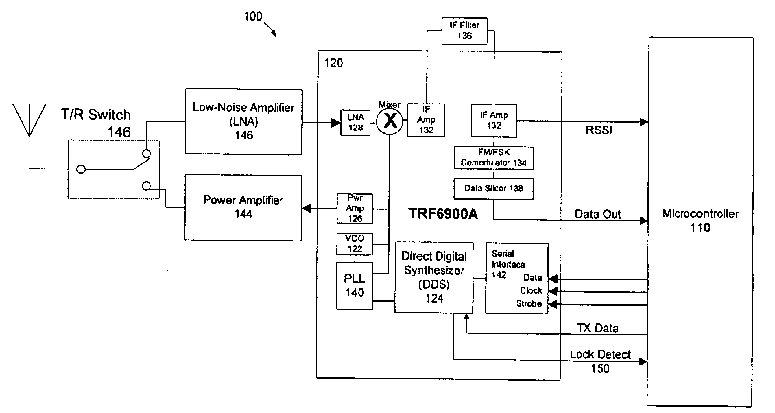
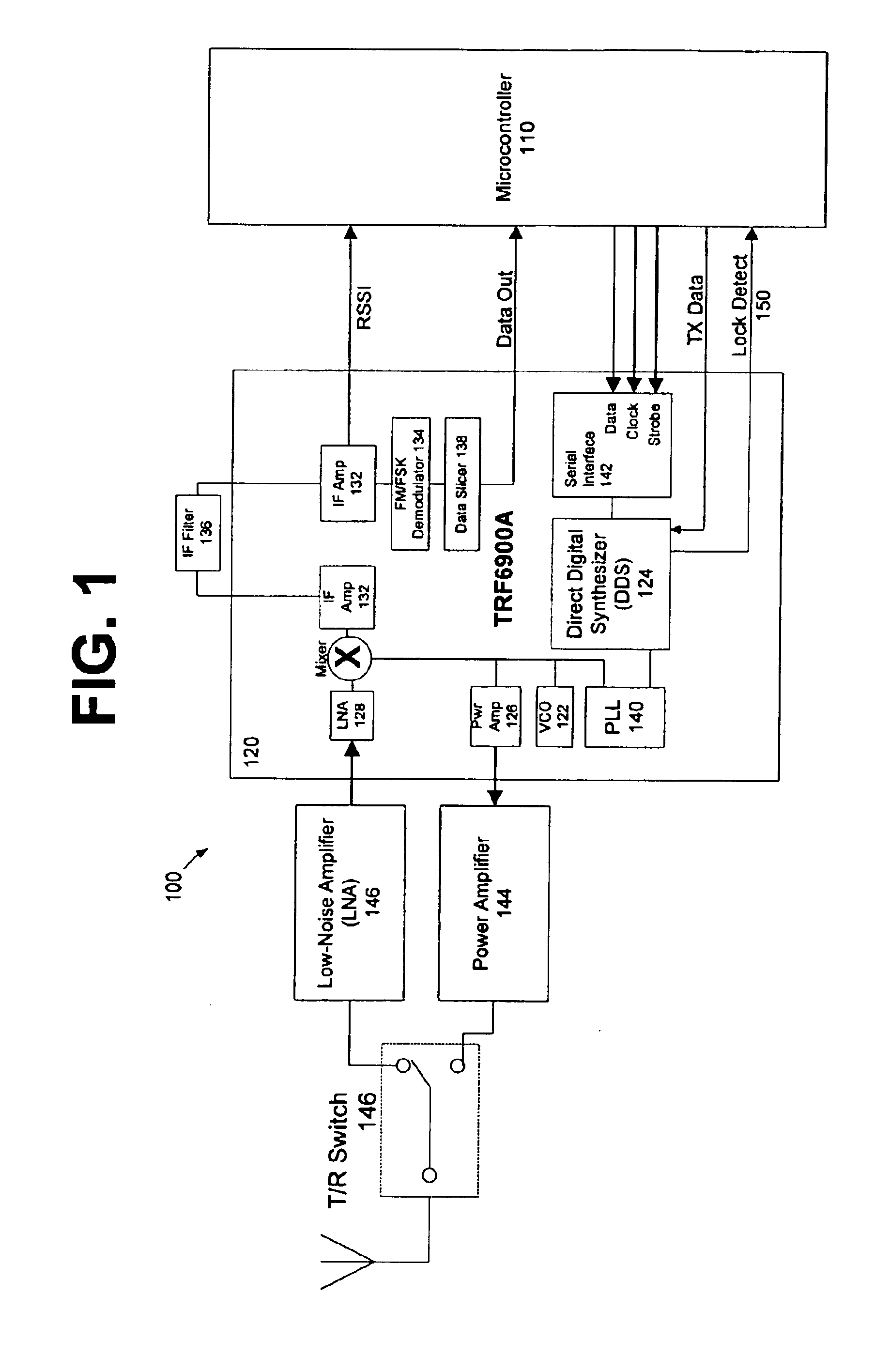
[0017]Referring now to FIG. 1, there is illustrated an exemplary embodiment of a frequency hopping radio 100 in accordance with the present invention. The present invention is controlled by a microcontroller 110 and preferably implemented using a Texas Instruments TRF6900 transceiver 120, which is an integrated circuit that includes an FSK transceiver to establish a frequency-agile, half-duplex, bi-directional RF link. The chip may be used for linear (FM) or digital (FSK) modulated applications in the North American 915-MHz ISM band.

[0018]The transmitter portion of the transceiver 120 consists of an integrated voltage controlled oscillator (VCO) 122, a complete fully programmable direct digital synthesizer 124, and a power amplifier 126. The receiver portion consists of a low-noise amplifier 128, mixer 130, IF amplifiers 132, limiter, FM / FSK demodulator 134 with an external LC tank circuit 136, and a data slicer 138.

[0019]The demodulator 134 may be used for analog (FM) and digital (...


PUM


Abstract

The present invention is directed to a frequency hopping spread spectrum transceiver. The transceiver includes a microcontroller; a transmitter having a voltage controlled oscillator, a direct digital synthesizer, and a power amplifier; and a receiver having an amplifier, a mixer, an IF amplifier, a demodulator, and a data slicer. When transmitting, the transmitter communicates a preamble over a predetermined number of preamble channels, and thereafter communicate groups of data bytes that each comprise a subset of the data message over a predetermined sequence of data channels. When receiving, the receiver investigates the predetermined number of preamble channels to search for the preamble, each of the predetermined number of preamble channels being associated with a predetermined number of data channels in each sequence of data channels. A number of bytes that comprises each group of data bytes is determined in accordance with a number of channels in the sequence of data channels and the predetermined number of times each byte of the data message is to be transmitted.

Description

FIELD OF THE INVENTION[0001]The present invention relates generally to the field of communications. More particularly, the invention relates to a frequency hopping spread spectrum technique by which messages are communicated via a limited number of channels to optimize packet timing and signaling efficiency.BACKGROUND OF THE INVENTION[0002]The fixed radio communications may operate using wire line or radio technology. Wire line technologies include utilizing the utility distribution lines and / or telephone lines. Wireless technologies may utilize the 902-928 MHz range, which can operate without a FCC license through the use of frequency hopping spread spectrum (FHSS) transmission, which spreads the transmitted energy over the band. According to FCC Regulations, for frequency hopping systems operating in the 902-928 MHz band, total output is as follows: 1 watt for systems employing at least 50 hopping channels; and, 0.25 watts for systems employing less than 50 hopping channels, but a...

Claims


Application Information

Patent Timeline
Patent Type & Authority Patents(United States)
IPC IPC(8): H04B1/69H04B1/713H04L1/04H04L1/02H04B1/7156
CPCH04B1/7156H04L1/04H04B2001/71566H04B2001/71563
Inventor MASON, JR., ROBERT T.HODGES, IV, EUGENE W.HEMMINGER, RODNEY C.SHUEY, KENNETH C.
Owner ELSTER ELECTRICTY LLC
Why Eureka
Try Eureka