Intelligent gain control in an on-frequency repeater

a repeater and intelligent technology, applied in the field of wireless access networks, can solve the problems of unreliable or non-existent service of individual wireless subscribers, unreliable coverage area of wireless networks, and individual subscribers cannot benefit from the improved services of repeaters

Inactive Publication Date: 2005-05-03
SPOTWAVE WIRELESS INC
View PDF19 Cites 168 Cited by
  • Summary
  • Abstract
  • Description
  • Claims
  • Application Information

AI Technical Summary

Benefits of technology

[0012]An object of the present invention is to provide an apparatus for automatically controlling gain throughout a wide operating range.

Problems solved by technology

At some point, usually dictated by economics, the build-out slows and / or becomes spotty leaving many individual wireless subscribers with unreliable or non-existent service.
These systems suffer the disadvantage in that an individual subscriber cannot benefit from the improved services afforded by the repeater unless they happen to be located within the coverage area of the repeater.
However, there are many instances in which wireless subscribers may reside or work in areas where the coverage area of the wireless network is unreliable.
Also, in-building coverage can be unreliable even within MSAs, depending on the size, location and construction of buildings and / or other obstacles.
In such cases, it may be uneconomical for a network provider to build-out the network to provide adequate coverage area, thereby leaving those subscribers with inadequate wireless services.
On the other hand, if the gain (in either the uplink or downlink paths) is too high, the repeater will radiate unnecessarily high signal powers to the subscriber's WCD and / or the base station.
In an environment in which there is more than one APR in use, radiation of excessive signal power in the downlink path can cause interference (in the form of multiple overlapping coverage areas) with other subscribers.
The same holds true for a single APR radiating excessive power in the downlink path causing interference to other subscribers outside the personal wireless space.
Similarly, radiation of excessive signal power to the base-station may cause interference with other base-stations and / or other users of the wireless communications network.
Typically, operation of the AGC becomes increasingly unreliable beyond the linear range of the VGA, and thus the performance of the AGC is typically limited by the linear range of the VGA.
Another difficulty typically encountered in on-frequency repeaters is system oscillation resulting from imperfect isolation between the two antennas.
However, this is a labor-intensive operation requiring skilled technicians using specialized equipment.
This increases the cost and complexity of installing the repeater, and thereby greatly discourages individual subscribers from acquiring a repeater for their personal use.

Method used


Image

  • Intelligent gain control in an on-frequency repeater
  • Intelligent gain control in an on-frequency repeater
  • Intelligent gain control in an on-frequency repeater

Examples


Embodiment Construction

[0032]The following description utilizes exemplary power levels, power ranges, channel frequencies and band-widths in order to illustrate various features of the present invention. Those skilled in the art will appreciate, however, that the present invention is by no means limited to such values. On the contrary, those skilled in the art will readily understand that the present invention can be deployed for use in conjunction with any wireless communications network, and it is to be expected that the power levels, power ranges, channel frequencies, and band-widths stated herein will be modified to conform to the requirements of the communications network in question. Such modifications are considered to be well within the purview of those of ordinary skill in the art, and lie within the intended scope of the appended claims.

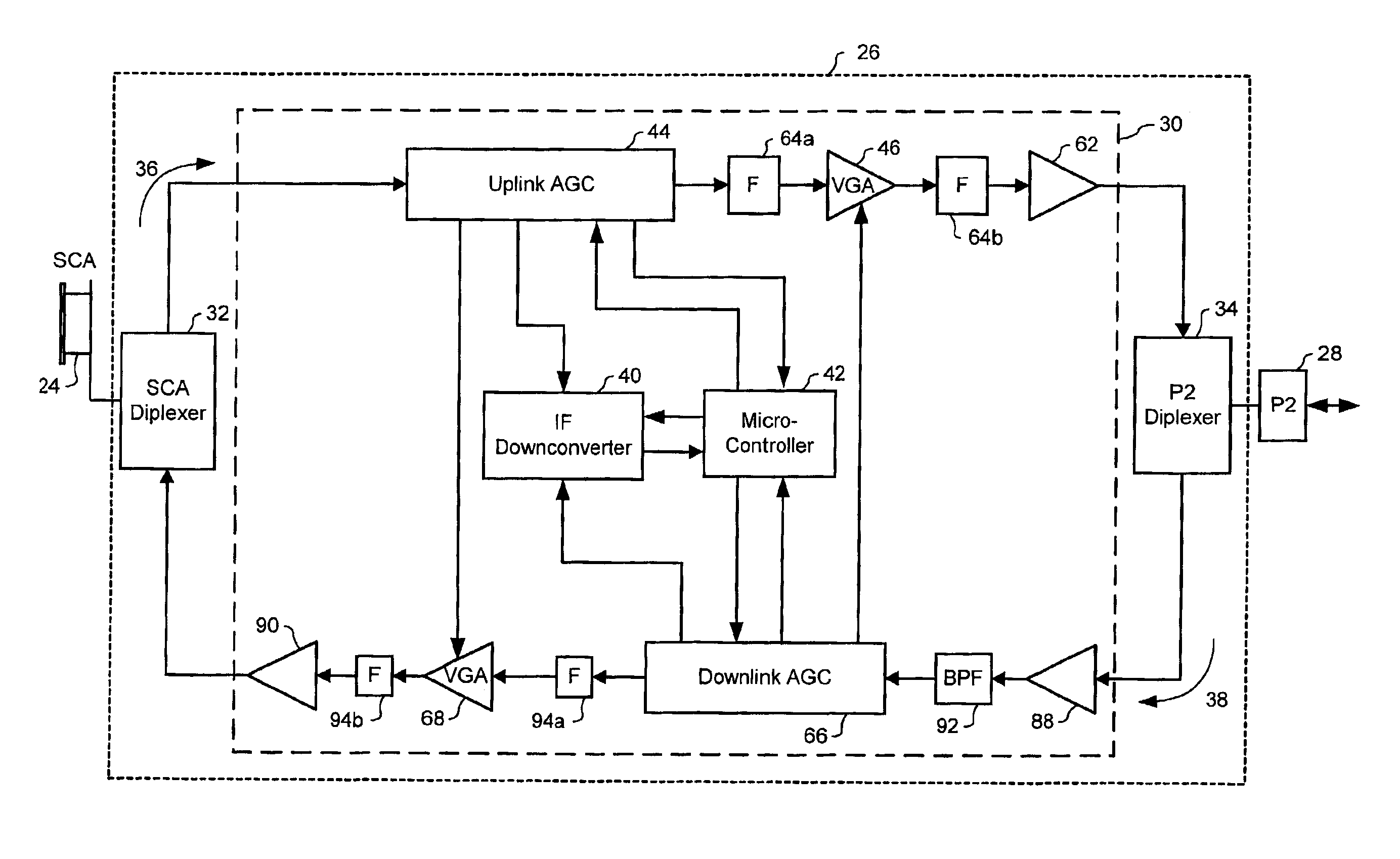
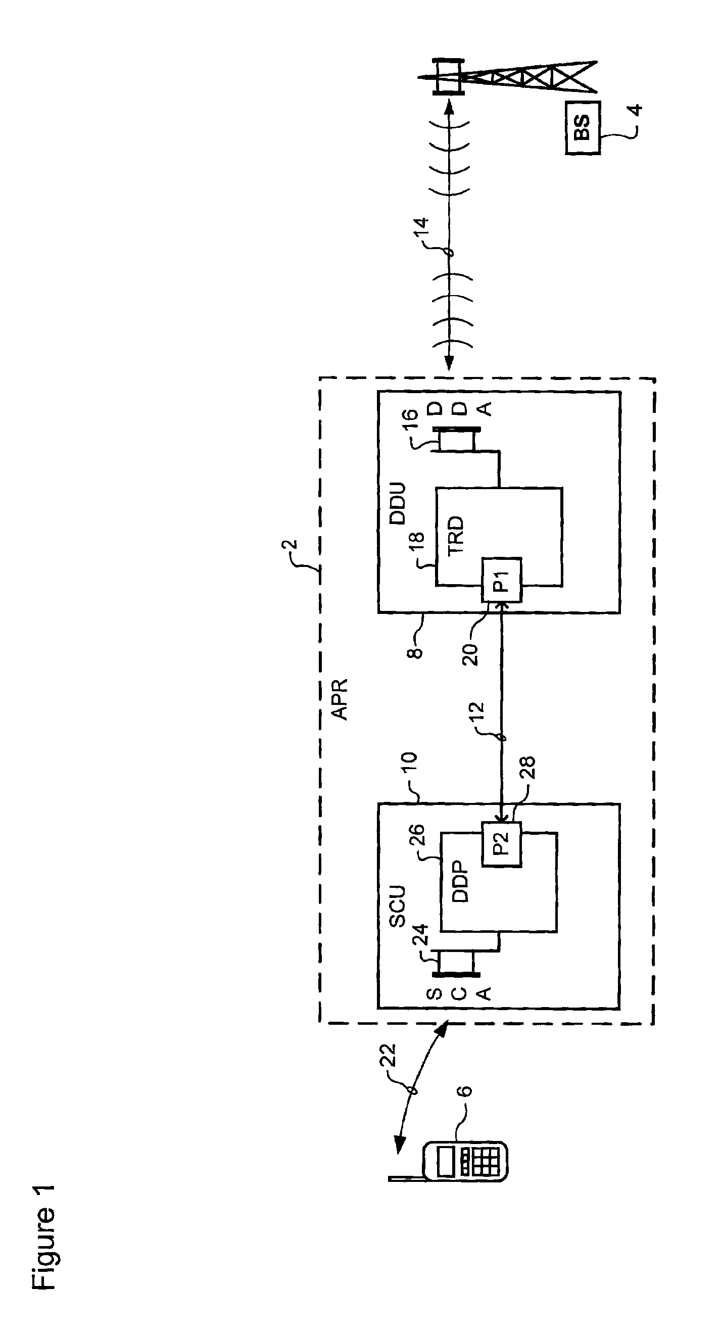
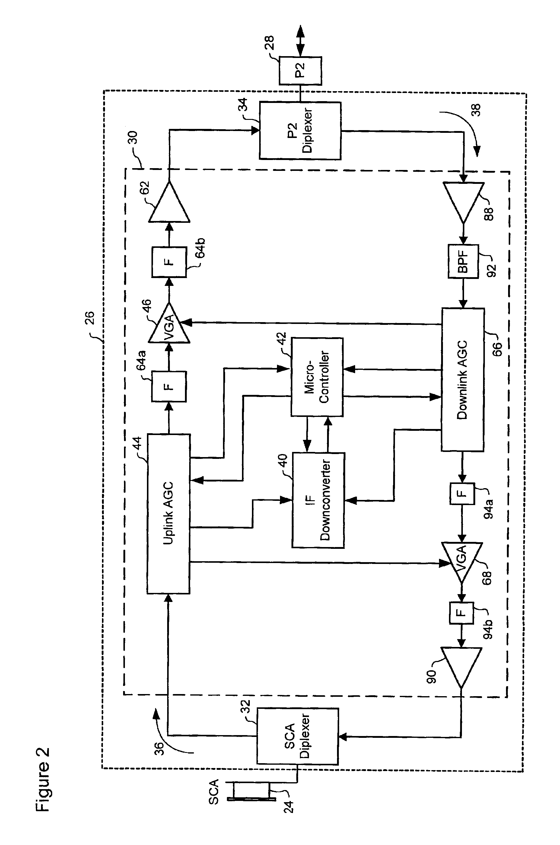
[0033]The present invention provides an Intelligent Gain Controller (IGC) for use in an on-frequency repeater, such as, for example, an Adaptive Personal Repeate...


PUM


Abstract

An intelligent gain controller operates to control the gain in each one of wideband uplink and downlink signal paths. Weak desired signals, within each wideband signal path, are detected using a narrowband down converter and detector, and these desired signals monitored by the micro controller. Based on the monitored signals, the micro controller operates, under control of suitable software implementing an Adaptive Control Algorithm, to adjust the gain in each of the uplink and downlink paths in order to dynamically optimize performance.

Description

CROSS-REFERENCE TO RELATED APPLICATIONS[0001]This application is related to the U.S. patent application Ser. No. 09 / 809,218, filed on Mar. 16, 2001.MICROFICHE APPENDIX[0002]Not Applicable.TECHNICAL FIELD[0003]The present application relates to wireless access networks and, in particular, to a method and system for enabling Intelligent Gain Control (IGC) in an on-frequency repeater.BACKGROUND OF THE INVENTION[0004]In the modern communications space, wireless access networks are increasingly popular, as they enable subscribers to access communications services without being tied to a fixed, wireline communications device. Conventional wireless access network infrastructure (e.g., base stations) is typically “built out”, by a network service provider, using a network-centric approach. Thus the build-out normally begins with major Metropolitan Service Areas (MSAs) using base stations located at the center of overlapping coverage areas or “cells”. The build-out, and corresponding wireles...

Claims


Application Information

Patent Timeline
Patent Type & Authority Patents(United States)
IPC IPC(8): H04B7/26H04B7/005H04B7/155H04Q7/36H04W16/26H04W52/10H04W52/52
CPCH04B7/15535H04B7/2606H04W52/52H04W52/10H04W16/26H04B7/15578
Inventor BONGFELDT, DAVID
Owner SPOTWAVE WIRELESS INC
Why Eureka
Try Eureka