High-Efficiency Envelope Tracking Systems and Methods for Radio Frequency Power Amplifiers

a radio frequency power amplifier and envelope tracking technology, applied in the direction of automatic control, process and machine control, instruments, etc., can solve the problems of inefficient input signal amplitude, fixed drain bias approach is not often a suitable approach to delivering power to an rfpa, and not very efficient converter of power, so as to achieve wide bandwidth and improve the efficiency of the regulator, and therefore the envelope modulator

Inactive Publication Date: 2009-07-30
APPLE INC
View PDF7 Cites 210 Cited by
  • Summary
  • Abstract
  • Description
  • Claims
  • Application Information

AI Technical Summary

Benefits of technology

[0011]Envelope tracking (ET) methods and systems for controlling the delivery of power to radio frequency power amplifiers (RFPAs) are disclosed. An exemplary ET system includes a wide-bandwidth-capable and power-efficient envelope modulator and an RFPA. The envelope modulator comprises a first switch-mode converter, a regulator (e.g., a linear regulator), and a second switch-mode converter. The first switch-mode converter has a power supply input configured to receive a direct current (DC) power supply voltage, a switch control input configured to receive a first switch control signal, and an output configured do provide a dynamic power supply signal. The regulator has an envelope signal input configured to receive an envelope signal, a power supply input configured to receive the dynamic power supply signal generated by the first switch-mode converter, and an output configured to provide current to the RFPA. The second switch-mode converter has a power supply input configured to receive the DC power supply voltage, a switch control input configured to receive a second switch control signal, and an output configured to provide current to the load. According to one aspect of the invention, the first switch control signal applied to the switch control input of the first switch-mode converter has signal characteristics relating to amplitude variations in the envelope signal received by the regulator, and the first-switch mode converter is configured to generate the dynamic power supply signal so that it tracks amplitude variations in the envelope signal. In this manner, the efficiency of the regulator, and therefore the envelope modulator, is significantly improved.

Problems solved by technology

Unfortunately, an RFPA powered by a fixed drain bias is not a very efficient converter of power.
Accordingly, in many applications, and in particular those that use non-constant-envelope signals, the fixed drain bias approach is quite often not a suitable approach to delivering power to an RFPA.
One significant drawback of the linear regulator, however, is that it is inefficient for input signal amplitudes that are lower than the magnitude of the DC supply voltage, Vsupply.
The inefficiency increases as this voltage difference widens.
While the switch-mode converter 400 in FIG. 4 is capable of generating an envelope modulated power supply signal efficiently, it is slow and noisy.
Filtering cannot completely remove the switching noise, and inevitably some amount of switching noise is introduced into the RF output signal, RFout, of the RFPA.
This switching noise makes it difficult to satisfy signal to noise ratio requirements required of wireless standards.
However, a large gate area introduces a large parasitic capacitance (on the order of 1000 pF), which limits the switching speed of the switching transistor 402 to only about 5 MHz or so.
Given that accurate envelope tracking requires a switching frequency of twenty to fifty times higher than the required signal envelope bandwidth, and many signal types have a signal envelope bandwidth of 1 MHz or higher, switch-mode converters are not typically well-suited for wide bandwidth ET tracking.
While the ET system 500 in FIG. 5 is capable of operating over a wide bandwidth, it is less efficient than desired.

Method used


Image

  • High-Efficiency Envelope Tracking Systems and Methods for Radio Frequency Power Amplifiers
  • High-Efficiency Envelope Tracking Systems and Methods for Radio Frequency Power Amplifiers
  • High-Efficiency Envelope Tracking Systems and Methods for Radio Frequency Power Amplifiers

Examples


Embodiment Construction

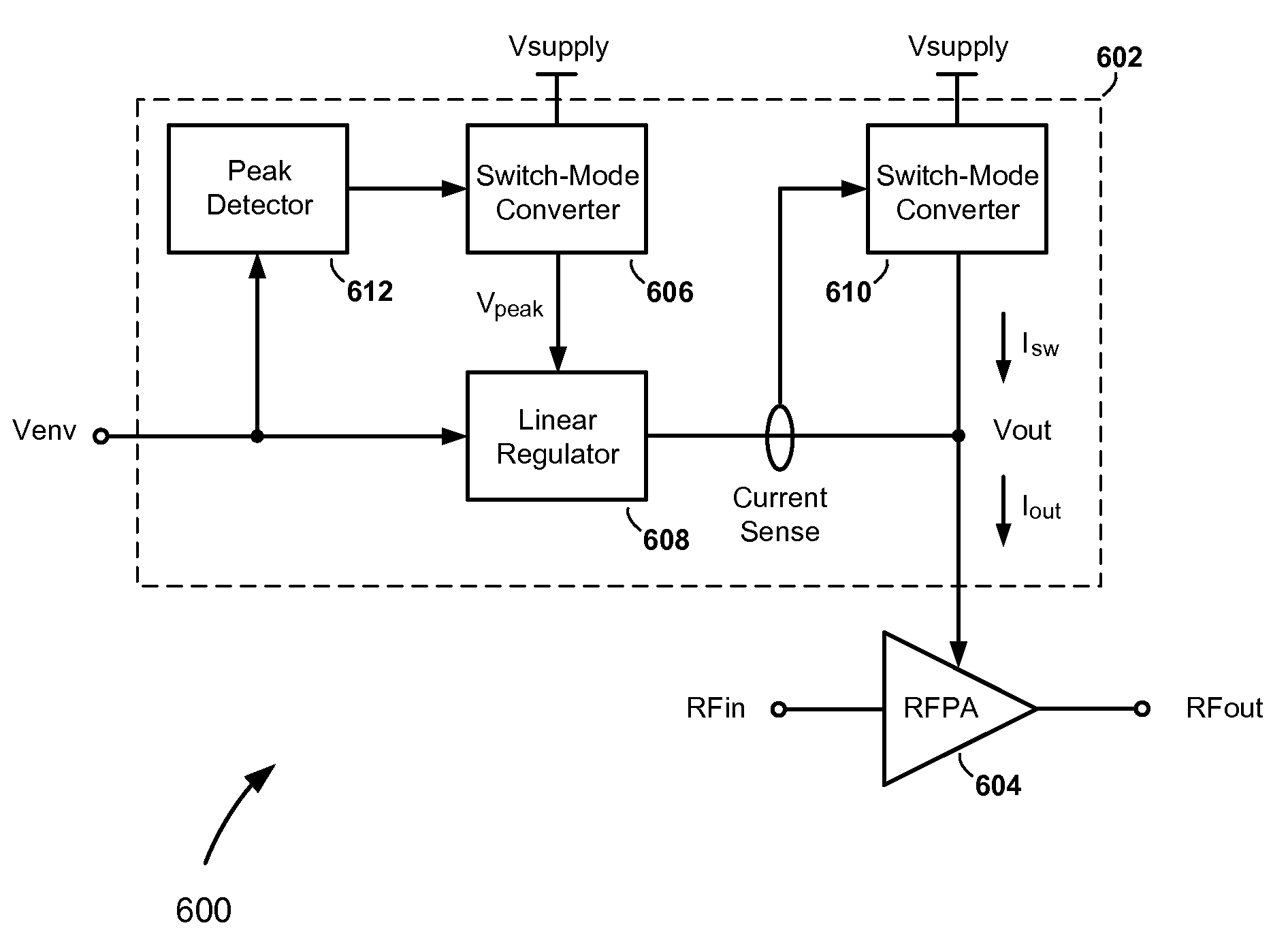
[0025]Referring to FIG. 6, there is shown an envelope tracking (ET) system 600, according to an embodiment of the present invention. The ET system 600 comprises an envelope modulator 602 and a radio frequency power amplifier (RFPA) 604. The RFPA 604 includes an RF input, which is configured to receive an RF input signal, RFin, an RF output, which is configured to provide an RF output signal, RFout, and a power supply input, which is configured to receive an envelope modulated power supply signal, Vout, from the envelope modulator 602. The envelope modulator 602 includes a first and second power supply paths, which are connected in parallel between a direct current (DC) power supply voltage, Vsupply, and the power supply input of the RFPA 604. The first power supply path includes a first switch-mode converter (e.g., a buck converter) 606 connected in series with a linear regulator 608. The second power supply path includes a second switch-mode converter 610.

[0026]According to an aspe...


PUM

PropertyMeasurementUnit
parasitic capacitanceaaaaaaaaaa
currentaaaaaaaaaa
voltageaaaaaaaaaa

Abstract

Envelope tracking (ET) methods and systems for controlling the delivery of power to radio frequency power amplifiers (RFPAs). An exemplary ET system includes an RFPA and a wide bandwidth capable and power efficient envelope modulator that includes a first power supplying apparatus and a second power supplying apparatus. The first power supplying apparatus includes a switch-mode converter and a regulator. The first mode converter is operable to dynamically step down a fixed power supply voltage according to amplitude variations in an envelope signal received by the regulator, and use the resulting dynamic power supply signal to power the regulator. The second power supplying apparatus is connected in parallel with the first power supplying apparatus. Depending on a power of an output signal to be generated at an output of the power amplifier, power is supplied to the power amplifier from either or both of the first and second power supplying apparatuses.

Description

FIELD OF THE INVENTION[0001]The present invention relates generally to controlling the delivery of power to radio frequency power amplifiers (RFPAs). More specifically, the present invention relates to high-efficiency envelope tracking (ET) systems and methods for controlling and supplying power to RFPAs.BACKGROUND OF THE INVENTION[0002]Radio frequency power amplifiers (RFPAs) are used in a wide variety of applications. As illustrated in FIG. 1, an RFPA 100 operates to convert an RF input signal, RFin, having a small amount of energy to an amplified RF output signal, RFout, having a large amount of energy. The energy required to complete this conversion process is provided by a direct current (DC) voltage supply, Vsupply, typically a battery.[0003]The approach to supplying power to the RFPA 100 in FIG. 1 is known as a “fixed drain bias” approach, since the drain of the transistor (typically, a field-effect transistor having a gate, a drain and a source) in the RFPA 100 is directly c...

Claims


Application Information

Patent Timeline
Patent Type & Authority Applications(United States)
IPC IPC(8): H04B1/04G05B24/02H03G3/00
CPCH03F1/0227H02M2001/0045H03G3/004H02M1/0045
Inventor TAKINAMI, KOJILIANG, PAUL CHENG-PO
Owner APPLE INC
Why Eureka
Try Eureka