Collision avoidance control system for vehicle

a control system and vehicle technology, applied in the direction of driver input parameters, external condition input parameters, electric devices, etc., can solve the problems of control lag, system operation load increase, and the inability of the above system to determine the degree of deceleration to be produced

Active Publication Date: 2005-05-03
DENSO CORP
View PDF14 Cites 43 Cited by
  • Summary
  • Abstract
  • Description
  • Claims
  • Application Information

AI Technical Summary

Benefits of technology

[0014]The collision avoidance deceleration determining circuit may decrease at least one of the minimum distance Dfin and the gain Ka as the distance D increases.
[0015]The collision avoidance deceleration determining circuit may also decrease at least one of the minimum distance Dfin and the gain Ka as one of a speed of the system vehicle and the relative speed Vr decreases.
[0016]The collision avoidance deceleration determining circuit may further decrease at least one of the minimum distance Dfin and the gain Ka as an intervehicle time (=D / Vm) derived by dividing the distance D by a speed Vm of the system vehicle and / or approach time (=D / |Vr|) derived by dividing the distance D by the relative speed Vr increase.
[0017]Specifically, when the minimum distance Dfin and the distance D to the target object are great sufficiently or when the speed Vm of the system vehicle or the relative speed Vr are small sufficiently, that is, when it is possible for a vehicle operator to turn a steering wheel to avoid the collision with the target object easily, the target collision avoidance deceleration G is lowered, thereby avoiding the deceleration of the system vehicle with which the vehicle operator feels uncomfortable.

Problems solved by technology

It is, however, impossible for the above systems to determine the degree of deceleration to be produced in an automatic braking device of the system vehicle to avoid collision with the preceding vehicle based on the determination of the danger of possible collision.
The system, however, has the drawback in that many mathematical operations are needed to determine the possibility of collision, thus resulting in a control lag.
The system also has an additional drawback in that when a range within which the preset deceleration is changed is fixed, it causes an operation load on the system to increase with a decrease in cyclic change in the preset deceleration, thus resulting in the need for limiting the magnitude of the cyclic change in the preset deceleration.
Specifically, it is difficult to determine the target deceleration as a continuously changing value, thus resulting in a difficulty in improving the accuracy of the deceleration control.

Method used


Image

  • Collision avoidance control system for vehicle
  • Collision avoidance control system for vehicle
  • Collision avoidance control system for vehicle

Examples


Embodiment Construction

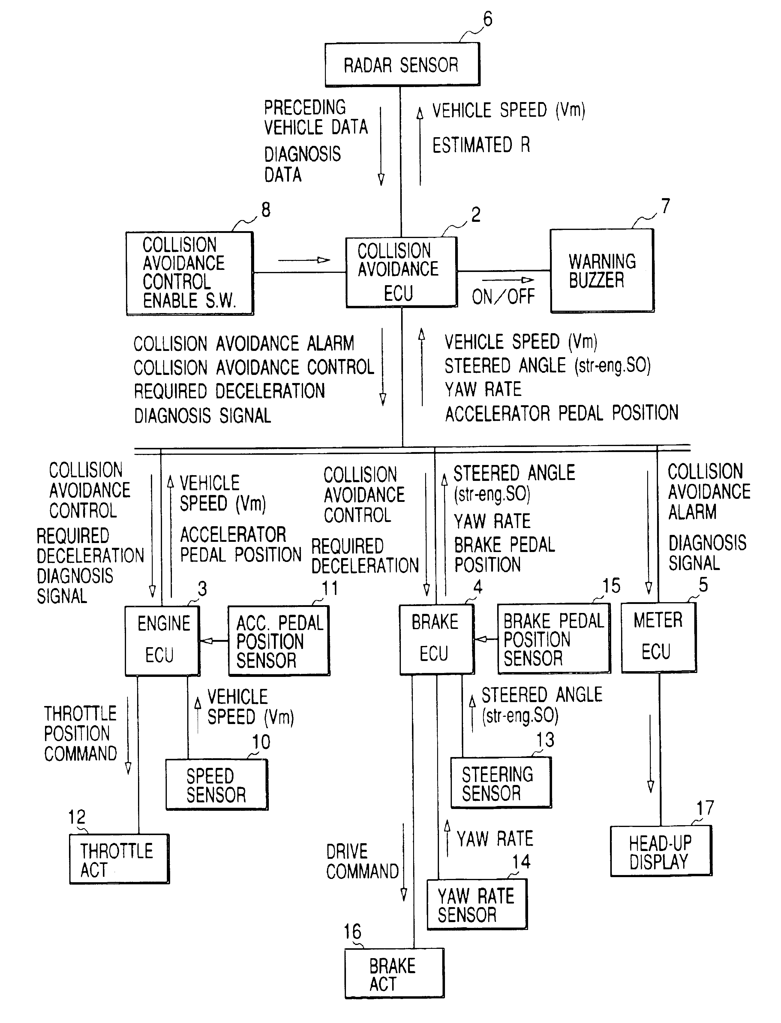
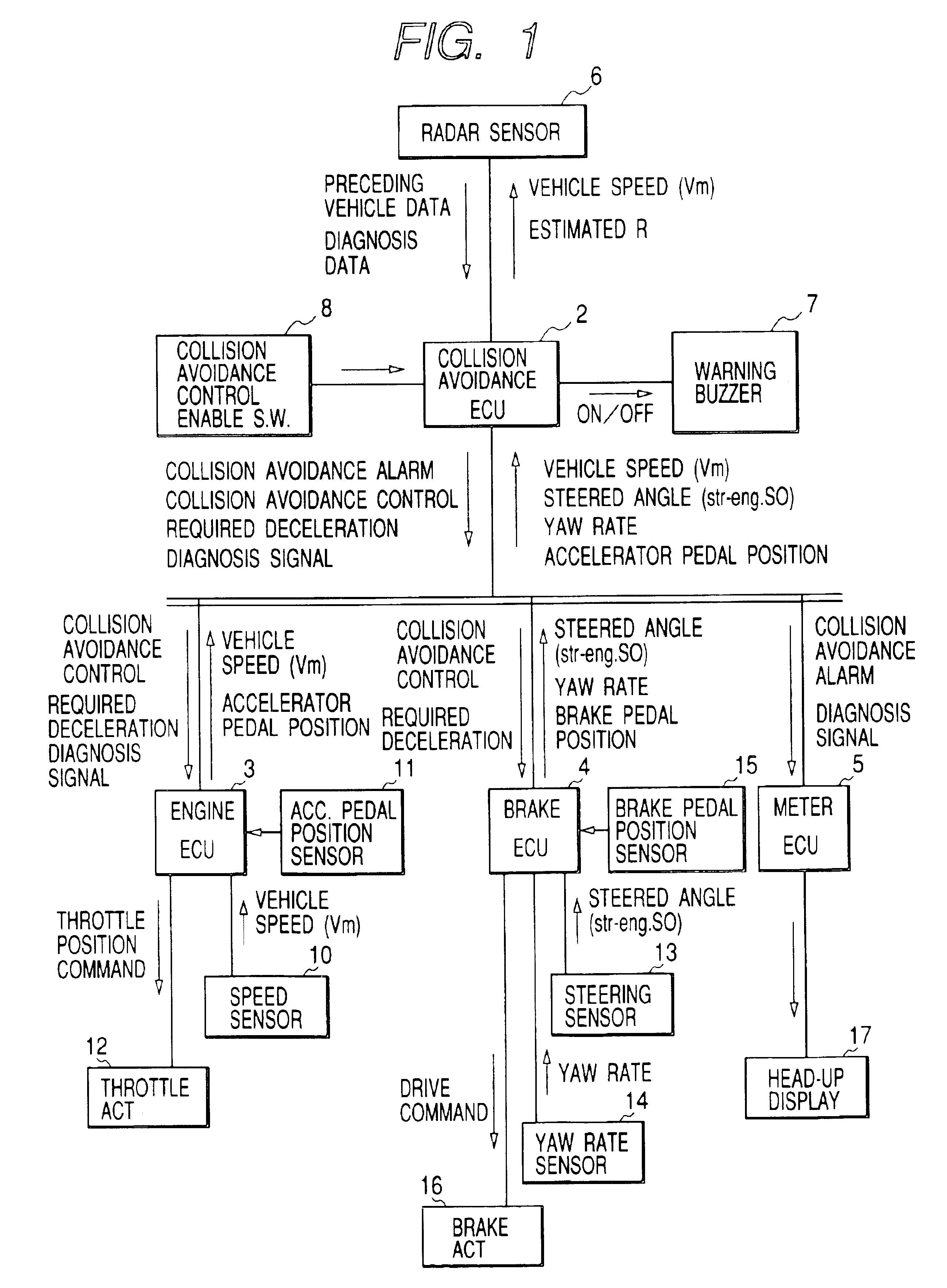
[0031]Referring now to the drawings, wherein like reference numbers refer to like parts in several views, particularly to FIG. 1, there is shown a collision avoidance control system according to the invention which may be employed in automotive vehicles to avoid accidental collisions with obstacles such as preceding vehicles running ahead. The following discussion will refer to, as an example, use in automotive vehicles. The collision avoidance control system consists essentially of a collision avoidance electronic control unit 2 (will also be referred to as a collision avoidance ECU below), an engine electronic control unit (will also be referred to as an engine ECU below) 3, a brake electronic control unit 4 (will also be referred to as a brake ECU below), and a meter electronic control unit 5 (will also be referred to as a meter ECU below) which are coupled to each other through a LAN communications bus. Each of the ECUs 2, 3, 4, and 5 is implemented by a typical microcomputer eq...


PUM


Abstract

A collision avoidance control system for a vehicle is provided which is designed to determine a target collision avoidance deceleration required for a system vehicle equipped with this system to bring a relative speed between the system vehicle and a target object into agreement with substantially zero without a physical collision with the target object and to determine a possibility of collision with the target object as a function of the target collision avoidance deceleration. When the possibility of collision is higher than a given threshold level, the system starts to decelerate the system vehicle. This enables the avoidance of collision with the target object at a decreased operation load on the system.

Description

BACKGROUND OF THE INVENTION[0001]1. Technical Field of the Invention[0002]The present invention relates generally to a collision avoidance control system which works to initiate collision avoidance action when the danger of possible collision with a target present ahead of a vehicle is encountered.[0003]2. Background Art[0004]Automotive collision monitor systems are known which work to estimate stopping distances of a system-equipped vehicle and a target preceding vehicle traveling ahead of the system-equipped vehicle and locations of the system-equipped vehicle and the target preceding vehicle after the elapse of a preset time to determine the danger of possible collision with the target preceding vehicle based on the stopping distances and the locations. For instance, Japanese Patent First Publication No. 08-132996 teaches such estimation of the stopping distances. Japanese Patent First Publication No. 05-181529 (corresponding to U.S. Pat. No. 5,473,538) teaches such estimation of...

Claims


Application Information

Patent Timeline
Patent Type & Authority Patents(United States)
IPC IPC(8): B60K31/00B60T8/1755B60T7/22B60T8/17G01S13/00G01S13/93G01S13/86G01S17/93G01S17/00B60R21/00G01S17/931B60T7/12B60W30/00B60W30/09B60W30/14F02D29/02G01S13/931G08G1/16
CPCB60K31/0008B60T8/17558G01S13/86G01S13/931G01S17/936B60T7/22G01S2013/9353B60T2201/02B60W30/09B60W2520/14B60W2550/302B60W2720/106G01S2013/9325G01S2013/9346G01S2013/935G01S2013/9319G01S2013/93185G01S2013/932G01S17/931B60W2554/804B60W2554/4042B60W2540/18B60W2050/143
Inventor ISOGAI, AKIRATERAMURA, EIJINISHIMURA, TAKAO
Owner DENSO CORP
Why Eureka
Try Eureka