
System and method for a self-calibrating non-invasive sensor

a non-invasive sensor and sensor technology, applied in the field of non-invasive sensing devices, can solve the problems of inability to accurately measure the accuracy of the measurement, the approach is too complex and expensive for practical manufacturing techniques, and the rejection of 40-60% of the component emitters

Inactive Publication Date: 2005-05-03
MEDTOR INC
View PDF84 Cites 159 Cited by
  • Summary
  • Abstract
  • Description
  • Claims
  • Application Information

AI Technical Summary

Benefits of technology

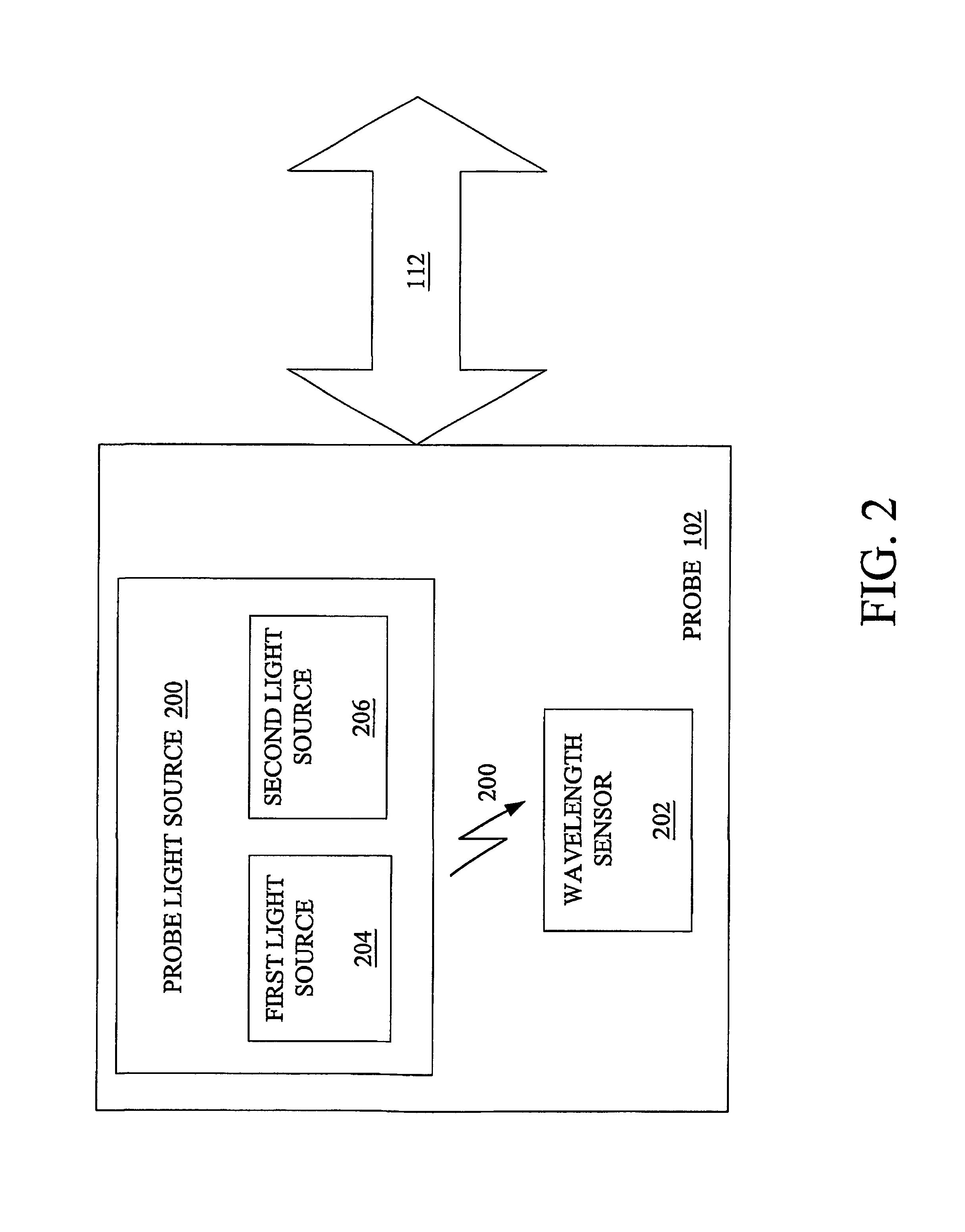
"The invention is a sensor system that can accurately measure the wavelength of light emitted from a light source over a wide range of wavelengths. It uses a calibration circuit to produce a calibrated signal based on the received incident light radiation. The sensor probe includes a wavelength sensor with two diodes that produce photocurrent signals for short and long wavelengths, respectively. The technical effect of this invention is to provide a reliable and accurate means for measuring light wavelengths, which can be useful in various applications such as optical communication systems or lighting control systems."

Problems solved by technology

Unfortunately, these types of non-invasive sensor systems utilizing a coherent light source require accurate prior knowledge of the wavelength of the coherent light source in order to determine the amount of coherent light that is absorbed or reflected through the target.
As an example, typical production techniques require selection of an emitter within 2 nm of a target wavelength, which may lead to rejection of 40-60% of the component emitters.
Moreover, an additional problem is that a selected emitter, which was within the target wavelength at time of production, will typically degrade over time, vary with temperature, and the drive circuit may become unstable and cause a wavelength shift.
Unfortunately, this approach is too complex and expensive for practical manufacturing techniques.

Method used


Image

  • System and method for a self-calibrating non-invasive sensor
  • System and method for a self-calibrating non-invasive sensor
  • System and method for a self-calibrating non-invasive sensor

Examples


Embodiment Construction

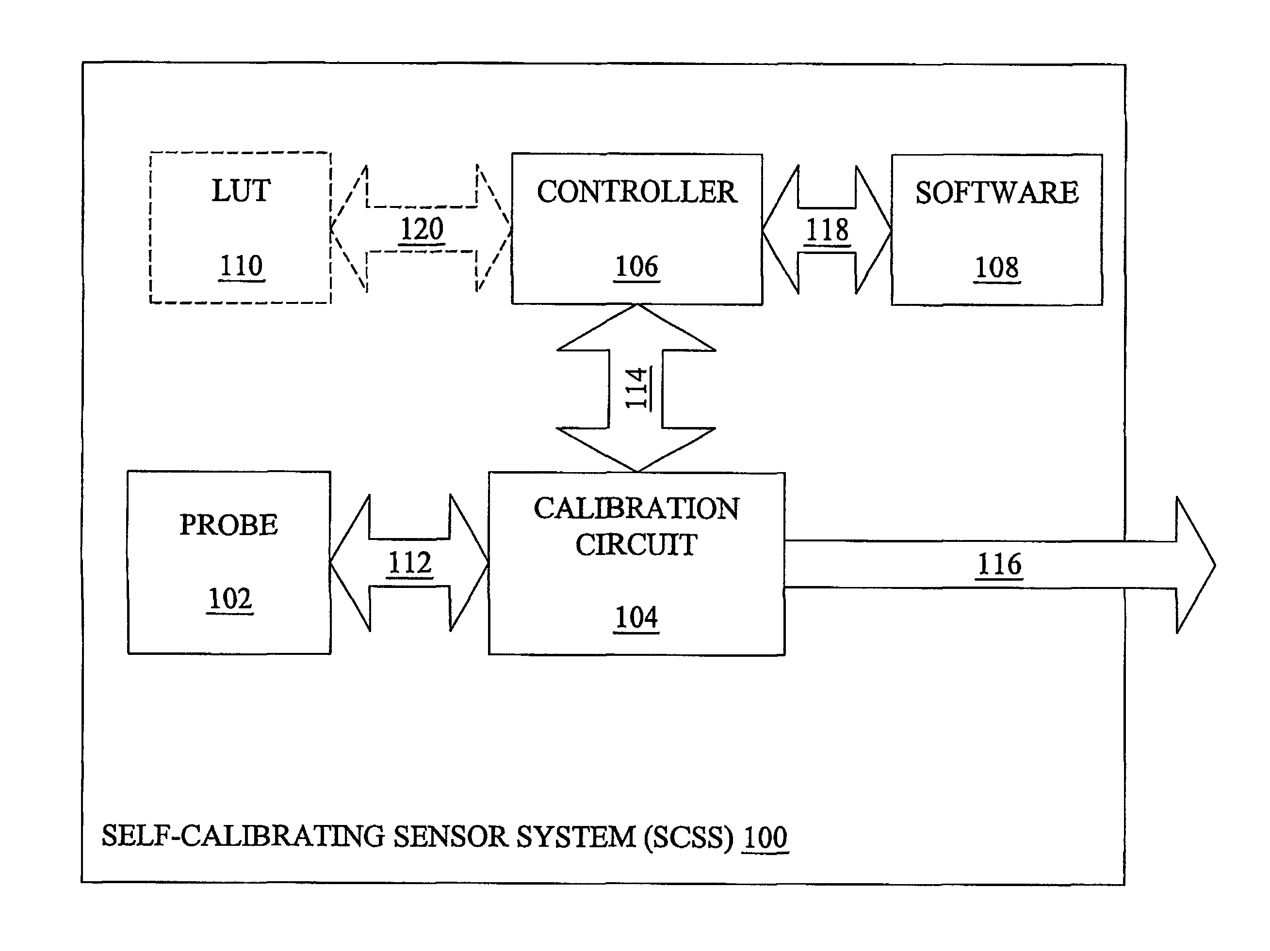
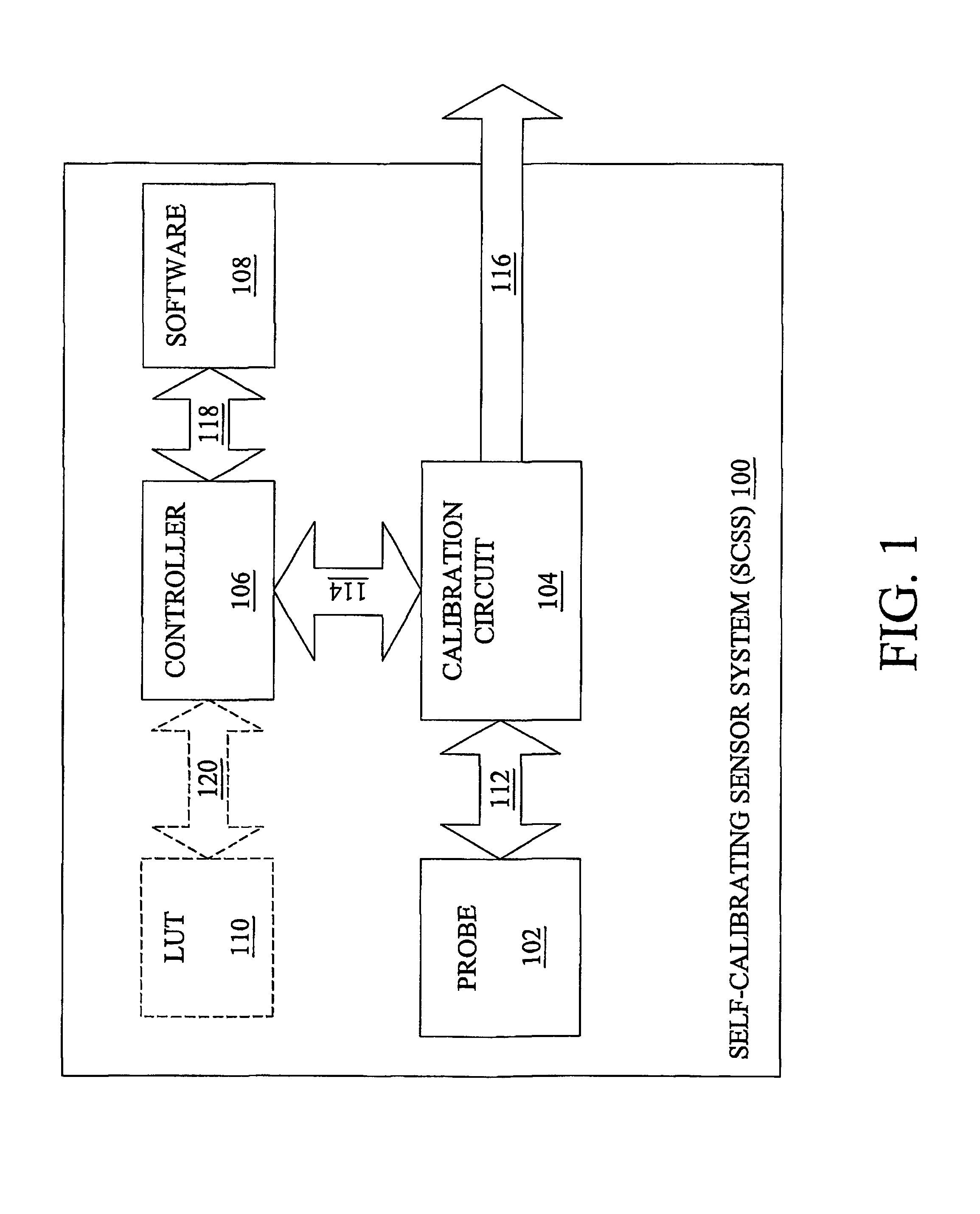
[0027]FIG. 1 illustrates a block diagram of a self-calibrating sensor system (SCSS) 100. The SCSS 100 may include a probe 102, a calibration circuit 104, a controller 106, software 108 located on in memory (not shown) and optional lookup table (“LUT”) 110. The probe 102 is in signal communication, via signal path 112, to the calibration circuit 104. The calibration circuit 106 may be a divider and / or comparator circuit.

[0028]The calibration circuit 104 is in signal communication to the controller 106 and an external output device (not shown) via signal paths 114 and 116, respectively. The controller 106 is in signal communication to software 108 and optional LUT 110 via signal paths 118 and 120, respectively.

[0029]The controller 106 may be any general-purpose processor such as an Intel XXX86, Motorola 68XXX or PowerPC, DEC Alpha or other equivalent processor. Alternatively, a specific circuit or oriented device may selectively be utilized as the controller 106. Additionally, the con...


PUM

PropertyMeasurementUnit
wavelengthaaaaaaaaaa
operating wavelengthaaaaaaaaaa

Abstract

A non-invasive emitter-photodiode sensor which is able to provide a data-stream corresponding to the actual wavelength of light emitted thereby allowing calibration of the sensor signal processing equipment and resulting in accurate measurements over a wider variation in emitter wavelength ranges.

Description

CROSS-REFERENCE TO RELATED APPLICATIONS[0001]This application claims the benefit of Provisional Patent Application Ser. No. 60 / 225,021 filed on Aug. 11, 2000 and entitled SELF CALIBRATING NON-INVASIVE BLOOD COMPONENT SENSOR.BACKGROUND OF THE INVENTION[0002]1. Technical Field[0003]This invention relates generally to non-invasive sensing devices, and in particularly to calibrating these non-invasive sensing devices.[0004]2. Related Art[0005]Coherent light sources are utilized in a broad range of applications in many distinct fields of technology including the consumer, industrial, medical, defense and scientific fields. In the medical field an emitter-receiver pair of coherent light sources in form of light-emitting diodes (LEDs) are often utilized in medical sensing devices to obtain accurate non-invasive measurements. An example application of such a medical sensing device may include a blood constituent monitoring system and / or a non-invasive oximeter that may be utilized to monito...

Claims


Application Information

Patent Timeline
Patent Type & Authority Patents(United States)
IPC IPC(8): A61B5/00G01N21/27G01N21/25
CPCA61B5/14551A61B5/14552A61B5/1495G01J9/00G01N21/274G01N21/35A61B5/14546A61B5/14532G01N21/3577G01J1/08G01J2003/2866G01N2021/3144G01N2201/1211G01N2201/12723H01L27/14647H01L31/03529G01N21/3504G01N21/3563
Inventor DIETIKER, THOMAS
Owner MEDTOR INC
Learn More