Optical recording medium and method of manufacturing the same

a technology of optical recording medium and manufacturing method, which is applied in the field of optical recording medium, can solve the problems of recording defect, reproduction defect, recording defect, etc., and achieve the effects of reducing deflection, excellent recording/reproducing performance, and less deflection and flutter

Inactive Publication Date: 2005-05-03
SONY CORP
View PDF27 Cites 10 Cited by
  • Summary
  • Abstract
  • Description
  • Claims
  • Application Information

AI Technical Summary

Benefits of technology

[0033]As explained above, according to the present invention, in the optical recording medium in which the information signal are configured to be capable of recording and / or reproducing an information signal is formed on a major surface of the disc substrate, and the light transmitting layer configured to be capable of transmitting therethrough the laser beam used in the process for recording and / or reproducing the information signal is formed on the side on which the information signal area is present, the clamp reference plane is defined in the portion on a major surface of the light transmitting layer. So, even if a foreign body is sandwiched between the clamp reference plane and the clamping unit (fixing jig) when the optical recording medium is chucked, the foreign body can be put so as to be embedded in the light transmitting layer. Thus, the flatness of the clamp reference plane can be maintained to thereby reduce the deflection on the optical recording medium as a final product. Hence, it is possible to attain the optical recording medium with less deflection and flutter, and being excellent in recording / reproducing performance.

Problems solved by technology

However, as a result of the various experiments by the inventor with regard to such an optical recording medium, it is confirmed, in the above-mentioned conventional optical disc, that when the optical disc is chucked and rotated at a predetermined rotation speed, a deflection (run out) of the disc becomes very large.
Such a deflection brings about a recording defect and a reproduction defect, in a case of an optical recording medium which has a higher NA of the objective lens of the optical system and a shorter wave length of the laser beam used in the recording and / or the reproduction.
For this reason, it results in a severe problem in a practical application of the optical recording medium having the improved recording density.

Method used


Image

  • Optical recording medium and method of manufacturing the same
  • Optical recording medium and method of manufacturing the same
  • Optical recording medium and method of manufacturing the same

Examples


first embodiment

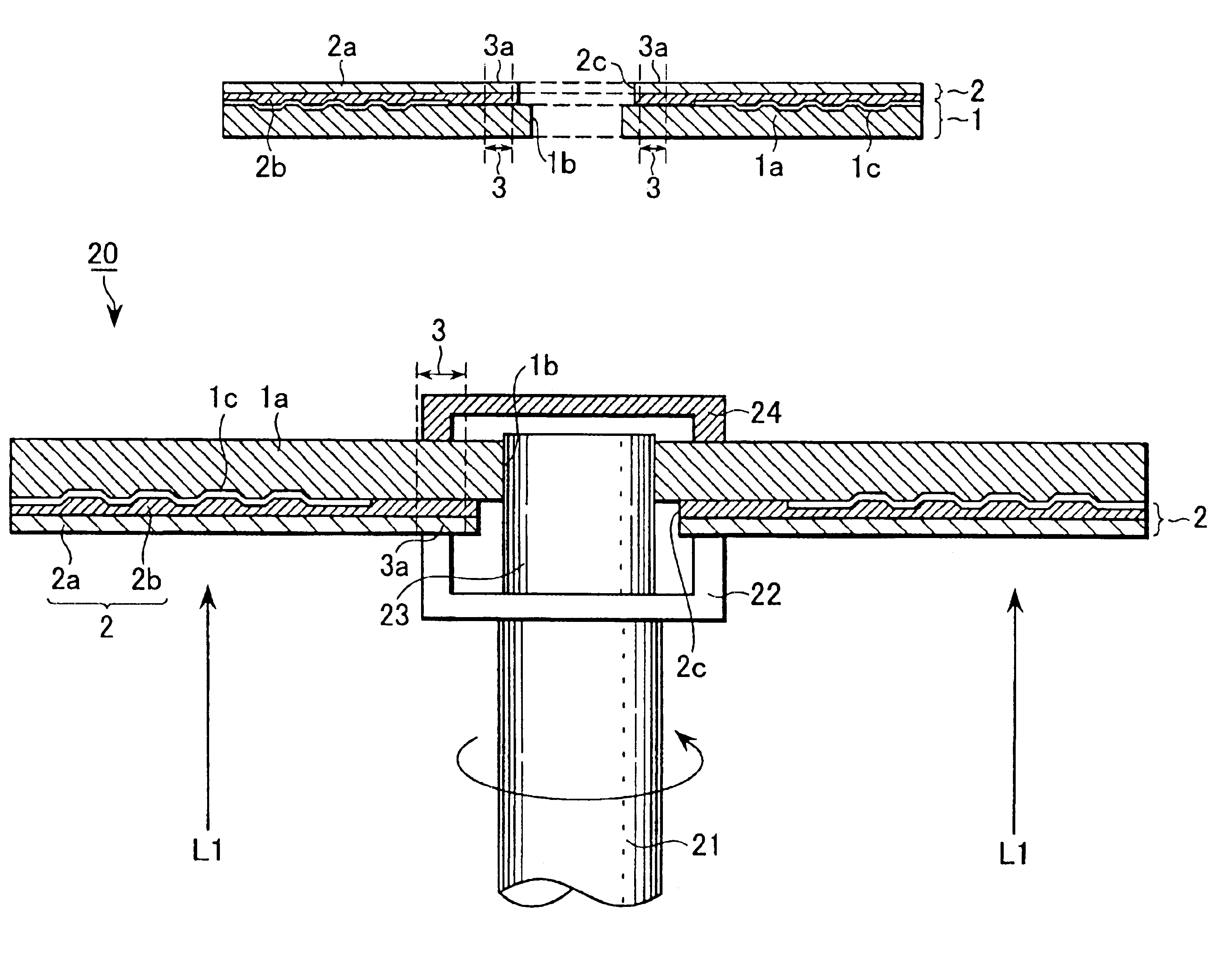
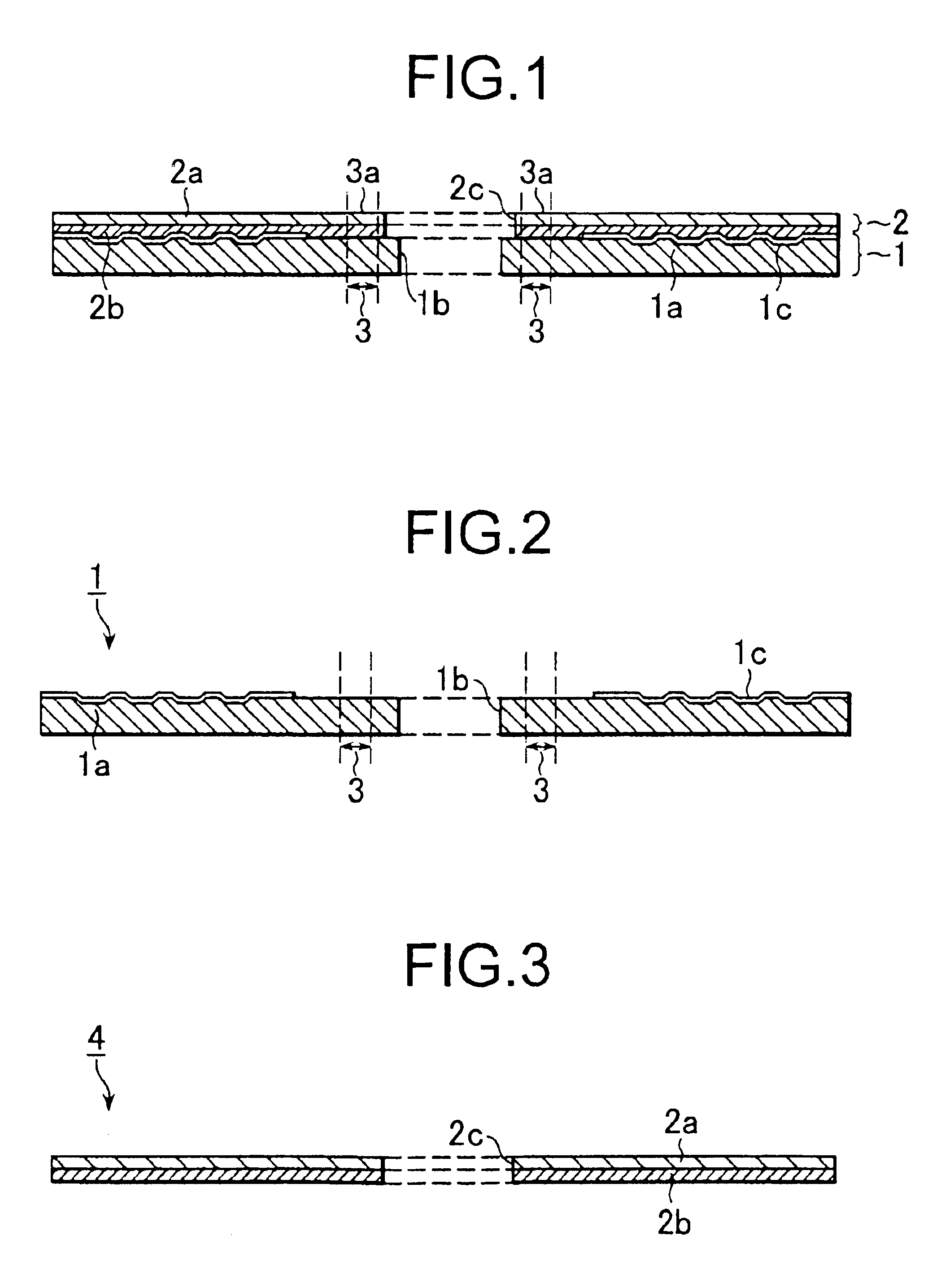
[0049]As shown in FIG. 1, in the optical disc a disc substrate 1 is configured such that a center hole 1b is formed at a center of a replica substrate 1a and an information signal area 1c is formed on a major surface on which concave and convex portions are formed. Also, a light transmitting layer 2 is formed on the disc substrate 1. The light transmitting layer 2 comprises a light transmitting sheet 2a and an adhesive layer 2b. The adhesive layer 2b is disposed between the light transmitting sheet 2a and the disc substrate 1 so as to adhere them. A penetration hole 2c is made at a center portion thereof. Here, a diameter of the penetration hole 2c is equal to or greater than a diameter of the center hole 1b, in consideration of the fact that the light transmitting sheet 2a is adhered onto the disc substrate 1 through the adhesive layer 2b. In specific, for example, the diameter of the penetration hole 2c is 15 mm or more.

[0050]Also, a clamp region 3 is annually arranged around the...

third embodiment

[0086]As shown in FIG. 11, the sheet used in the third embodiment comprises the light transmitting sheet 41a. The light transmitting sheet 41a has a structure formed by punching flatly and annually, similarly to the disc substrate 1, and a penetration hole 41c is formed at a center portion thereof. Here, as the size of the light transmitting sheet 41a, a diameter (outer diameter) is less than the outer diameter of the replica substrate 1a (for example, 120 mm). For example, in this case, the diameter o the light transmitting sheet 41a is 119 mm. A diameter of the penetration hole 41c, that is, an inner diameter of the sheets is equal to or greater than the open diameter of the center hole 1b (actually, for example, 15 mm or more) and also equal to or less than the inner circumference diameter of the clamp region. Specifically, for example, the diameter of the penetration hole 41c is set at 22 mm.

[0087]Also, the light transmitting sheet 41a is made of, for example, a thermoplastic re...


PUM

PropertyMeasurementUnit
diameteraaaaaaaaaa
diameteraaaaaaaaaa
diameteraaaaaaaaaa

Abstract

There is provided an optical recording medium, in which a light transmitting layer is formed on a disc substrate, having less deflection and being excellent in recording/reproducing properties. In an optical disc, an information signal area on which an information signal can be recorded and/or reproduced is formed on a major surface of a disc substrate thereof; a light transmitting layer which can transmit a laser beam used in a process for recording and/or reproducing the information signal is formed on a side on which the information signal area is present; and a clamp reference plane is arranged on a major surface of the light transmitting layer in a clamp region. If the optical disc is clamped by a chucking unit of a drive, it is clamped by making the clamp reference plane on the major surface of the light transmitting layer contact with a mounting surface of a table for mounting the disc, and making a magnetic metal plate contact with the major surface of the disc substrate, and then sandwiching the optical disc between.

Description

CROSS REFERENCES TO RELATED APPLICATIONS[0001]The present document is based on Japanese Priority Document JP 2000-307201, filed in the Japanese Patent Office on Oct. 6, 2000, the entire contents of which being incorporated herein by reference.BACKGROUND OF THE INVENTION[0002]1. Field of the Invention[0003]The present invention relates to an optical recording medium and a method of manufacturing such optical recording medium. More particularly, the present invention is preferable for an application to an optical recording medium on and from which an information signal is recorded and / or reproduced, by radiating a laser beam from a side on which a light transmitting layer is formed, to an optical disc having a recording layer and a light transmitting layer formed on a substrate.[0004]2. Description of the Related Art[0005]In recent years, various researches and developments with regard to an optical information recording method have been promoted in a field of information recording. T...

Claims


Application Information

Patent Timeline
Patent Type & Authority Patents(United States)
IPC IPC(8): G11B7/26G11B7/24G11B11/105G11B11/00G11B7/24024G11B7/24047G11B7/24056G11B7/24067G11B7/254G11B7/257
CPCG11B7/24G11B7/26G11B11/10582B29L2017/005B29C65/1435B29C65/1483B29C65/483B29C65/521B29C66/452B29C65/1406B29C65/484B29C65/4815B29C65/4825B29C65/4845G11B7/24027
Inventor KIKUCHI, MINORUNAKANO, JUN
Owner SONY CORP
Why Eureka
Try Eureka