
Coupling device for locking push-on couplings of tools

Active Publication Date: 2005-05-10
EDUARD WILLE GMBH & CO KG
View PDF20 Cites 22 Cited by
  • Summary
  • Abstract
  • Description
  • Claims
  • Application Information

AI Technical Summary

Benefits of technology

[0012]It is an object of the invention, to construct a coupling device for locking a push-on coupling by means of easy to manufacture and, therefore, inexpensive components.
[0015]This provides a simple, in particular easy to manufacture and, therefore, inexpensive design, which can be realized substantially by turned parts and bores only. The actuating body is moved forward under the action of the spring means through the cam surface, so that the ball is moved into its locking position. For quick release of coupling, the releasing element is pushed down against the action of the spring. Then, the cam surface releases the actuating body, so that the actuating body yields upon exertion of radial force on the ball without resistance and permits radial yielding of the ball, also without substantial resistance. The contact surface between the actuating body and the ball is very little, exactly only a contact point. Furthermore the contact surface between the actuating body and the cam surface is very little as well, exactly only a contact line. Therefore the movements in all are easy-running. In this manner the construction is not susceptible to contamination.
[0017]Thereby, the actuating body, in its extended position in which the ball is in its locking position, is safely supported against axial forces, which might be exerted by the ball. The actuating body is in a well-defined position.

Problems solved by technology

Mere push-on couplings are unsafe and can easily get loose.
This may require considerable force, as also large and, thereby, heavy sockets have to be retained safely on the square.
As the screw or nut often cannot be reached with the normal tool, extension bars or connecting tools such as universal joints or adaptors are required.
The prior art structures described above require complex parts and, therefore, can only be manufactured with considerable expenditure.
Also this arrangement is very expensive both with respect to the design and with respect to the manufacturing.

Method used


Image

  • Coupling device for locking push-on couplings of tools
  • Coupling device for locking push-on couplings of tools

Examples


Embodiment Construction

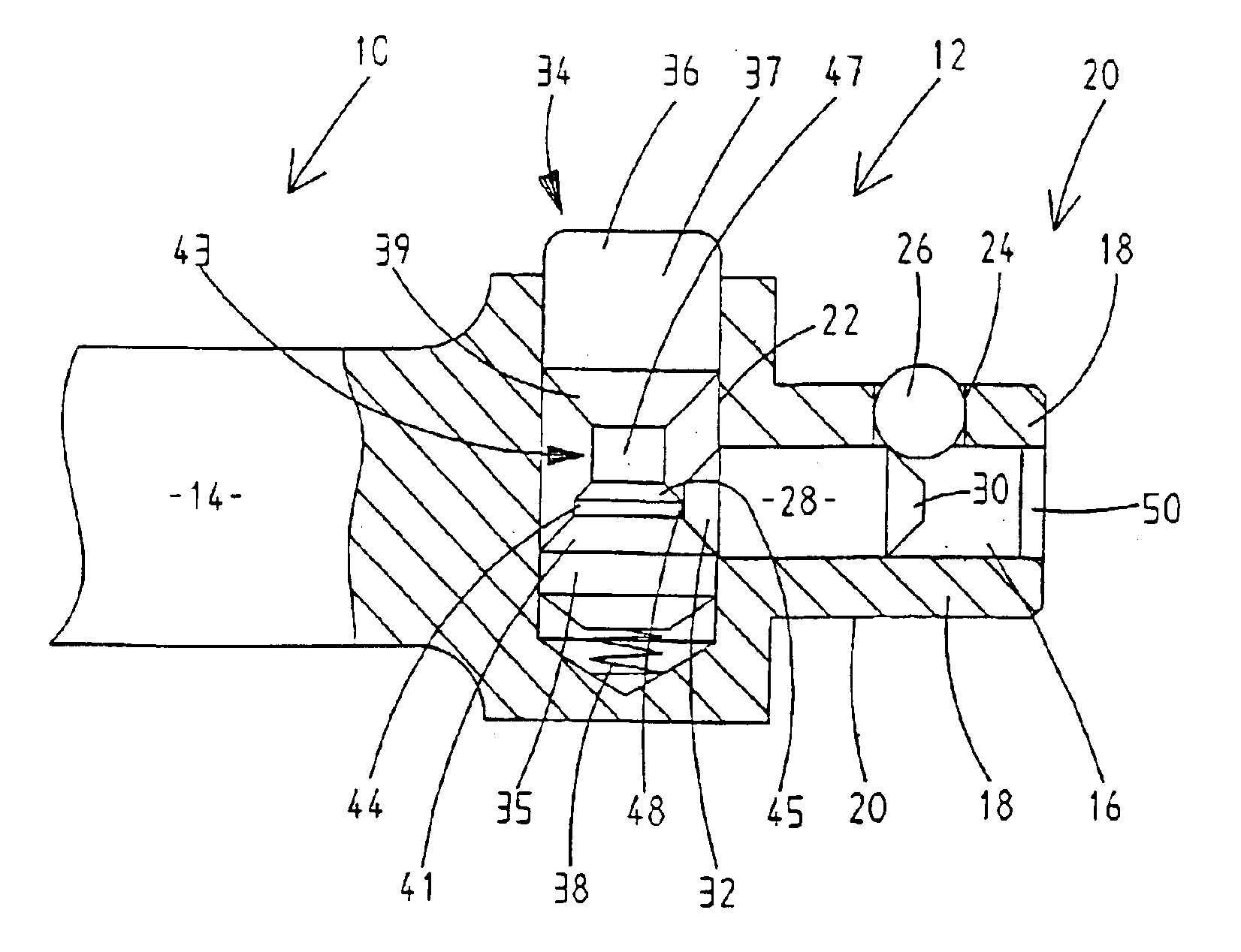
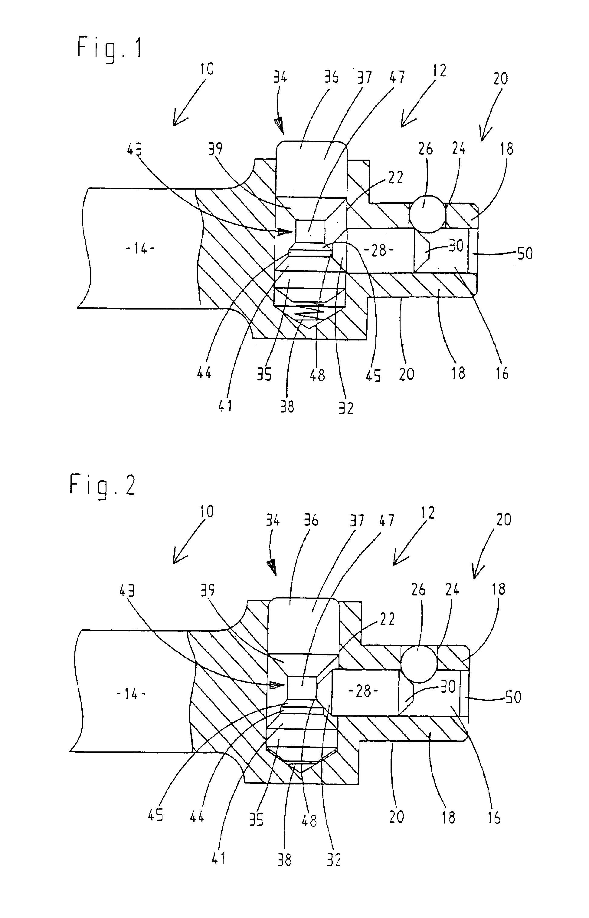
[0023]FIG. 1 illustrates, in sectional view, part of an actuating tool or connecting part, for example an extension rod 10 with quick release 12 for sockets. The extension rod 10 has a body 14. At one end of the body 14 is an axial, longitudinal passage 16 in the form of a bore. The axial longitudinal passage 16 is surrounded by side faces 18 of a polygonal coupling body 20. A transverse bore 22 in the form of a blind bore is provided normal to the axial longitudinal passage 16 and intersects this passage. A ball 26 is provided in a transverse bore 24 opening in a side face 18 of the polygonal coupling body 20. An actuating body 28 is guided in the longitudinal passage 16. The ball 26 can be either sunk into the polygonal coupling body 14 or caused to project therefrom depending on the position of the actuating body 28. Well-known means for limiting the outward movement of the ball 26 are provided at the transverse bore 24.

[0024]The actuating body 28 is conical at its ends 30, 32. B...


PUM


Abstract

A coupling device includes a polygonal coupling part on one of the parts to be coupled for engaging a complementary polygonal counterpart on another of the parts to be coupled. The polygonal coupling part has outer side faces, a longitudinal bore therein, and a first transverse bore with a ball therein intersecting the longitudinal bore and one of the side faces. An actuating body tapering at first and second ends is guided for longitudinal movement in the longitudinal bore between an extended position wherein the first end moves the ball radially into a locking position and a retracted position permitting inward movement of the ball out of its locking position. A second transverse bore intersecting the longitudinal bore guides a releasing element having a cam surface engaging the second end of the actuating body. The releasing element is movable against the action of a biasing spring to move the actuating body from its extended position to its retracted position.

Description

TECHNICAL FIELD[0001]The invention relates to a coupling device for locking push-on couplings especially of tools, the coupling device being releasable by actuating a releasing element to permit easy detaching of the push-on coupling. The push-on coupling comprises a polygonal coupling part on one of the parts to be coupled for engaging a complementary polygonal counterpart on another of the parts to be coupled. The polygonal part has a longitudinal passage or bore. The longitudinal bore communicates with a transverse bore intersecting the longitudinal bore and opening in a side face of the polygonal coupling part. A ball is guided in the transverse bore. An actuating body is longitudinally movable in the longitudinal bore. A tapering end of the actuating body engages the ball, whereby longitudinal movement of the actuating body in the longitudinal bore to an extended position causes the ball to move outwards into a locking position. Longitudinal movement of the actuating body into ...

Claims


Application Information

Patent Timeline
IPC IPC(8): B25B23/00F16B7/20F16D1/10
CPCB25B23/0035Y10T403/599Y10T403/592
Inventor WILHELM, JOACHIM
Owner EDUARD WILLE GMBH & CO KG
Features
  • Generate Ideas
  • Intellectual Property
  • Life Sciences
  • Materials
  • Tech Scout
  • Unparalleled Data Quality
  • Higher Quality Content
  • 60% Fewer Hallucinations
Learn More