Inhalator with aerosolizing unit

an inhalator and air technology, applied in the direction of inhalators, medical atomizers, moving spraying apparatus, etc., can solve the problems of unoptimized inhalators, and untimely delivery of drugs, etc., and achieve the effect of low cos

Inactive Publication Date: 2005-05-10
SHL MEDICAL AG
View PDF9 Cites 170 Cited by
  • Summary
  • Abstract
  • Description
  • Claims
  • Application Information

AI Technical Summary

Benefits of technology

[0014]According to the invention, a mechanical breath actuated inhalator is provided. Due to its mechanical working, the inhalator requires no external energy source, which makes it reliable under all circumstances.
[0015]A mechanical inhalator according to the invention, such as an inhalator according to any one of the embodiments shown in the detailed description, allows the manufacturing of a reliable inhalator at a relatively low cost.
[0016]Furthermore, the present invention makes it possible to design an inhalator for “puffing” a pharmaceutics, i.e. a certain dosage of a pharmaceutics could be inhaled by several breathings in stead of inhaling the entire dosage in one single breath. For example, this allows a patient to inhale nicotine in a way that very much resembles smoking.

Problems solved by technology

It has been found that such inhalators are not optimal in that the delivered drug is not always introduced effectively into the respiratory passages of the patient.
The coordination between the inhalation and the triggering of the drug delivery is critical and introduces the risk of an untimely administration with respect to the breathing.
In addition, the breathing cycle and strength differs between different patients which introduces another difficulty.
However, even with such unit dosage inhalators it is possible that the pharmaceutics is not inhaled in the most effective way.
This is a disadvantage in many applications, where low cost and small size is desired.
In addition thereto, the need for electric energy makes the device vulnerable under circumstances where new batteries or an external energy source are not obtainable.

Method used


Image

  • Inhalator with aerosolizing unit
  • Inhalator with aerosolizing unit
  • Inhalator with aerosolizing unit

Examples


first embodiment

[0038]an aerosolizing unit 10 according to the invention for use in an inhalator is shown in FIGS. 1 to 6.

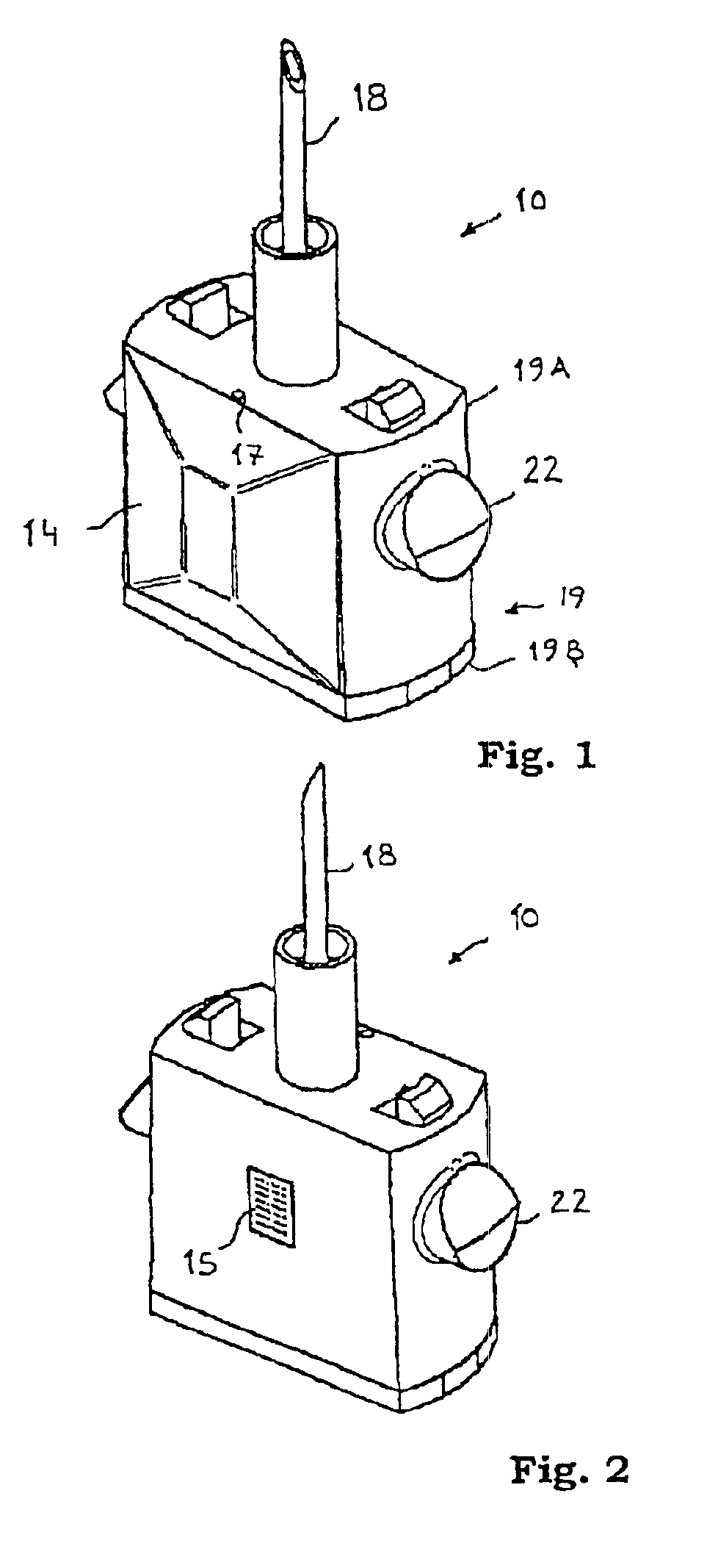
[0039]FIG. 1 shows the aerosolizing unit 10 from an angle wherein a flexible membrane 14 mounted at one side of on a body 19 is visible, as well as a generally tubular conduit, i.e. a hollow needle 18, for coupling a liquid container thereto. The body 19 consists of an upper body section 19A and a lower body section 19B.

[0040]FIG. 2 shows the other side of the aerosolizing unit 10 of FIG. 1, wherein a porous membrane 15 is visible. The aerosolizing unit 10, which is adapted to be mounted in a generally tubular air conduit by means of a couple of protruding fastening means 22, will now be described in detail.

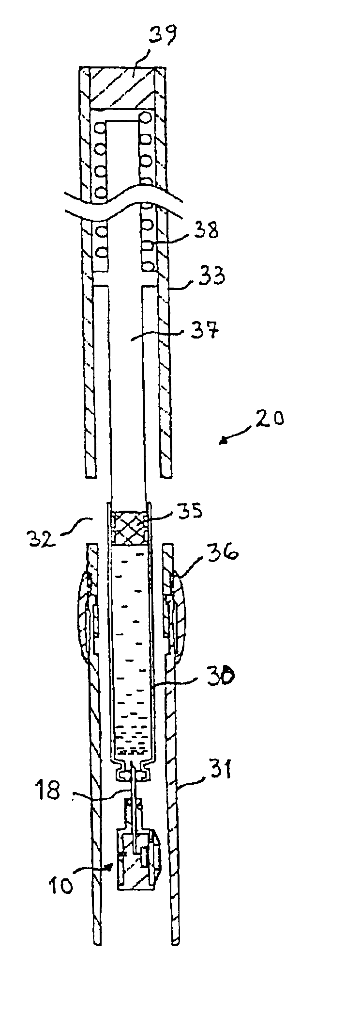
[0041]An embodiment of a complete inhalator 20 according to the invention including the aerosolizing unit 10 of FIGS. 1 and 2 is shown in the perspective view of FIG. 3. The inhalator has an upper section 33 containing a drug container (not visible in FIG. 3), a lower section...

second embodiment

[0065]a handheld portable small size inhalator according to the present invention shall now be described with reference to FIGS. 6 to 9.

[0066]In the perspective view of FIG. 6 is shown a second embodiment of an aerosolizing unit 110 to be attached to the mouthpiece of the inhalator by fastening means 122. A generally tubular conduit, i.e. a needle 118 for coupling to the drug cartridge is attached to the body 119 of the aerosolizing unit 110. A porous membrane 115 for delivering the drug in an aerosolized form is visible at the end of the body 119.

[0067]The aerosolizing unit 110 of FIG. 7 shall now be explained with reference to the cross sectional views of FIGS. 7, 8 and 9. Also, reference is made to the first embodiment as described above for the understanding of corresponding features.

[0068]The unit 110 is mounted within a mouthpiece 131 using the fastening means 122. The mouthpiece is hollow to provide a flow path for inhaled air. At its upper end the flow path exhibits a first ...

third embodiment

[0081]FIGS. 10-13 show an aerolizing unit where the same components as the previous embodiments have the same reference numbers. The aerolizing unit 200 is attached in the mouthpiece 31 of the inhaler in a suitable manner via a lower 202 and an upper 204 support piece. The support pieces are attached to each other by two fins or wings 206 extending radially from the longitudinal axis 208 of the aerolizing unit, FIG. 11. The lower support piece is arranged with a generally tubular, downwardly protruding holder 210. The end of the holder is arranged with a circumferential recess 212, in which a valve unit 214 is arranged. The valve unit comprises a circular lid 216 with a central opening 218 connecting to a passage arranged in an elongated tubular part 220 of the valve unit. Outside the opening a porous membrane 222, preferably a Rayleigh membrane is arranged. The passage has a first diameter and accommodates a metallic magnetically affectable ball 224, such as a steel ball. The passa...


PUM


Abstract

A portable, handheld breath actuated inhalator, to aerosolize and distribute a pressurised liquid, including a breath flow path defined between an air inlet (132) and a mouthpiece (131) outlet, a container (30) for the liquid, an aerosolizing element (115) for introducing the aerosolized liquid into the breath flow path, a valve element (113) between the container and the aerosolizing means for allowing fluid communication between the container and the aerosolizing element, and an actuator to regulate the valve element. The actuator is mechanical and is energized by the flow of inhaled air.

Description

[0001]This application is a 371 of PCT / SE00 / 02099 dated Nov. 2, 2000.TECHNICAL FIELD OF THE INVENTION[0002]The present invention relates to a portable handheld inhalator for the administration of a pharmaceutically active substance, and more specifically to a portable handheld inhalator being actuated by the breath of the patient.TECHNICAL BACKGROUND OF THE INVENTION[0003]There is a general need for portable handheld inhalators. A common group of inhalators are those that deliver an aerosolized drug in a fixed unit dosage when an actuator is pressed, squeezed or pulled by the patient.[0004]It has been found that such inhalators are not optimal in that the delivered drug is not always introduced effectively into the respiratory passages of the patient. The coordination between the inhalation and the triggering of the drug delivery is critical and introduces the risk of an untimely administration with respect to the breathing. In addition, the breathing cycle and strength differs betw...

Claims


Application Information

Patent Timeline
Patent Type & Authority Patents(United States)
IPC IPC(8): A61M15/00A61M15/06A61M11/00
CPCA61M15/0091A61M15/0093A61M11/007A61M15/06
Inventor OLSSON, THOMAS
Owner SHL MEDICAL AG
Why Eureka
Try Eureka