Bar screen

a bar screen and bar screen technology, applied in the field of bar screens, can solve the problems of conflicting requirements, increasing production costs and environmental loads, and not always being able to maintain the conditions required for making strong and clean pulp, etc., to achieve the effect of improving continuous cooking and its control, superior hydraulic properties, and high expansion and circulation flows

Inactive Publication Date: 2005-05-10
VALMET TECH INC
View PDF14 Cites 19 Cited by
  • Summary
  • Abstract
  • Description
  • Claims
  • Application Information

AI Technical Summary

Benefits of technology

[0013]The invention is based on an idea got during an empirical study that because the greatest pressure difference in a screen is not in the gap but deeper within the plug flow, the back part of the gap can be used as a channel of the vertical flow. If it is not sufficient in size, other parts of the background of the screen are utilised by adjusting the partition. It has also been proven by tests that round shapes provide advantageous friction between the screen and the plug flow. Round shapes also provide superior hydraulic properties.
[0014]The bar screen of the invention provides considerable advantages. The screen bars of the bar screen do not have sharp corners to which the cooked wood or pulp could fasten and where it could cut. Because a bar screen of this kind enables a substantial reduction in this kind of fastening, no other material, either, is fastened to the bar screen that might disturb the plug flow and filtering when accumulating.
[0015]The bar screen construction of the invention enables continuously high expansion and circulation fl...

Problems solved by technology

The requirements are in conflict unless cooking conditions are carefully optimized.
Because even a partial blocking of expansion and circulation screens causes channelling and disturbed flows in the digester, and often also production losses, it is not always possible to maintain the conditions required for making strong and clean pulp.
This is of course a very negative matter, because it causes an increased use of raw material, energy and chemicals, which again increases production costs and environmental loads.
Sometimes, blocking also causes the screens to break when the support structures fail.
One problem with this known screen construction is that it has a relatively high tendency to block when chips fasten to the gaps.
A softened chip particle is also easily cut by the sharp edges of the screen bars, which also tends t...

Method used


Image

  • Bar screen
  • Bar screen
  • Bar screen

Examples


Embodiment Construction

[0037]A preferred embodiment of the present bar screen is in the following described with reference to the above-mentioned figures. The bar screen comprises structural parts marked with reference numbers in the figures and corresponding to the reference numbers used in this description.

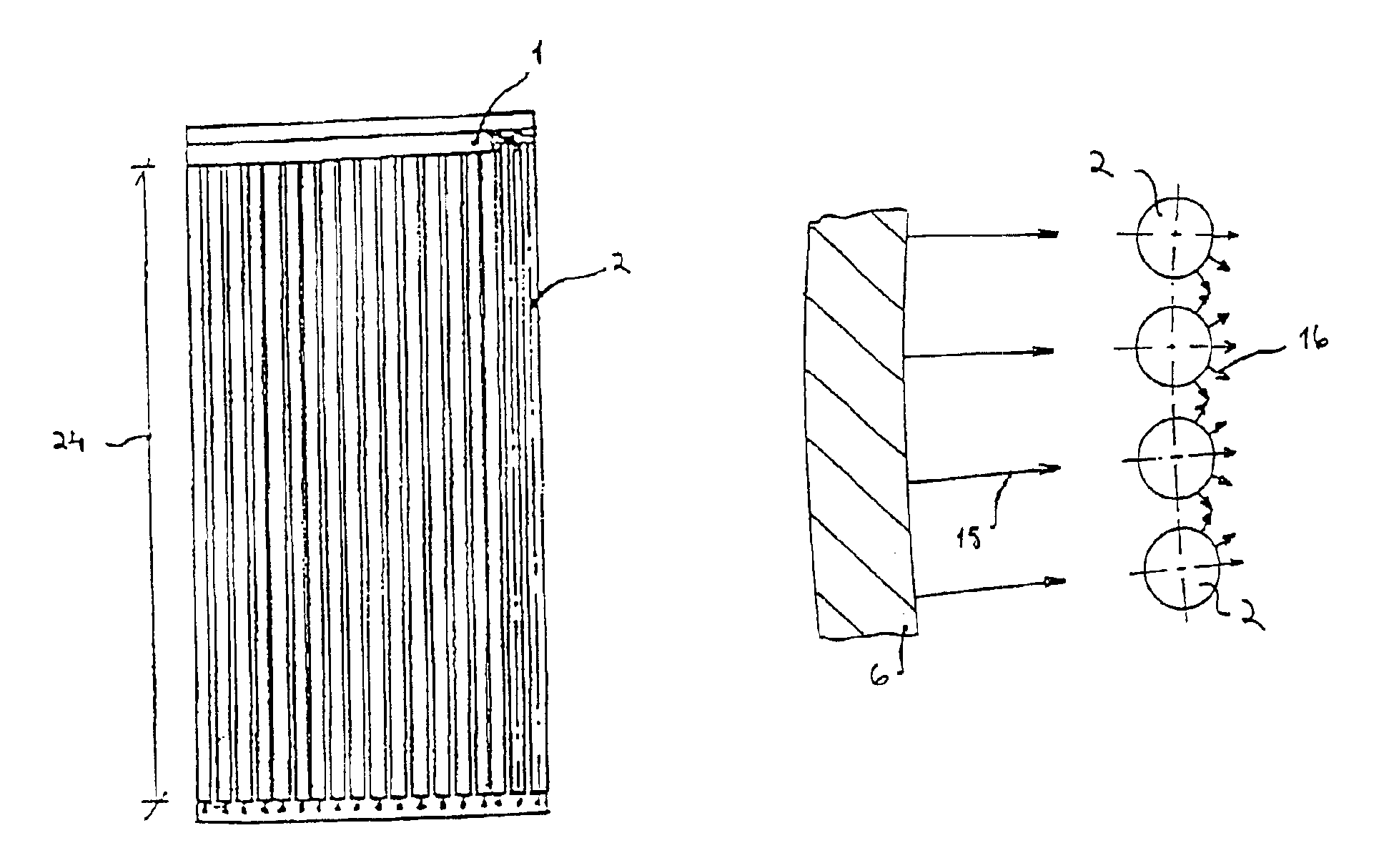
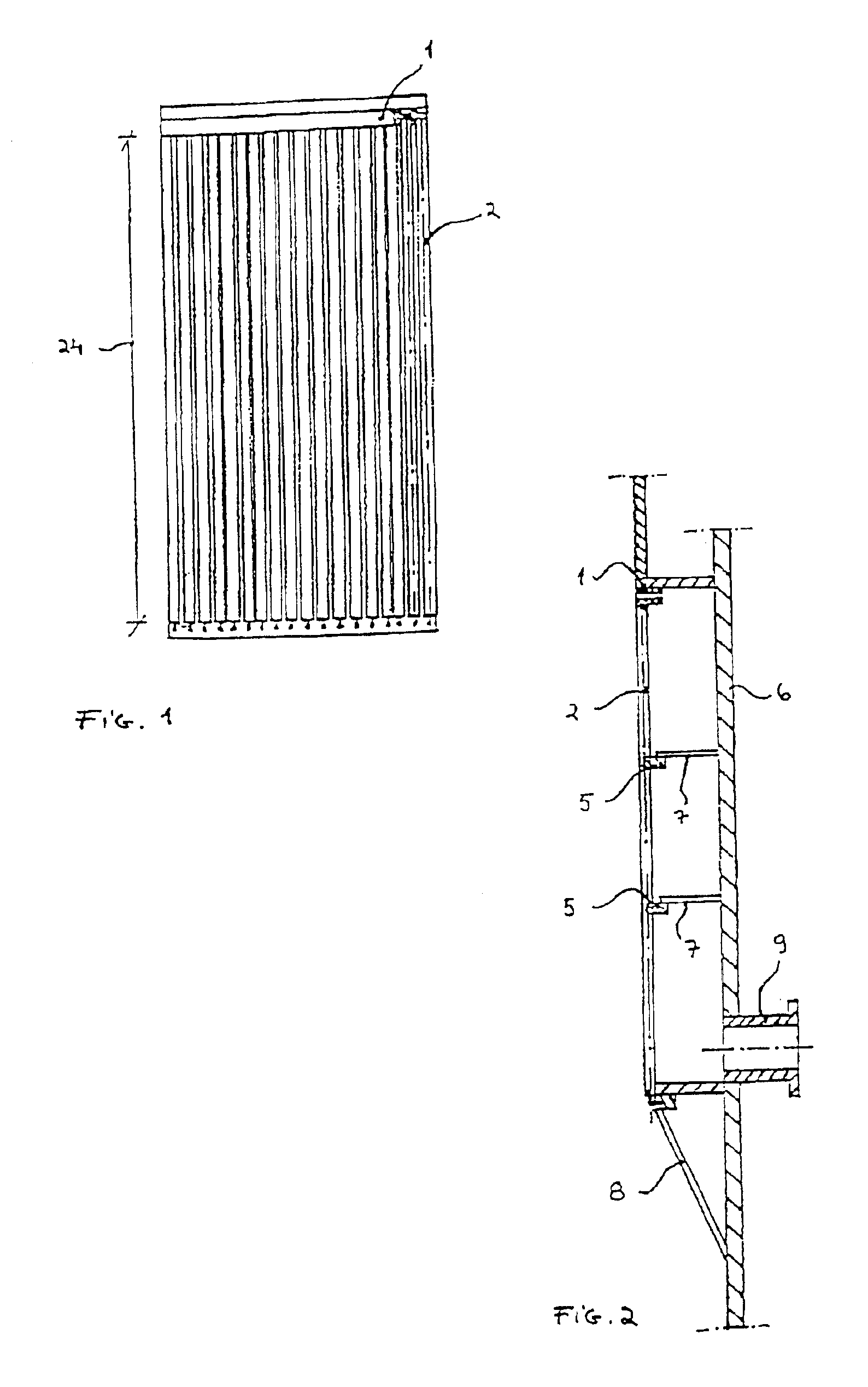
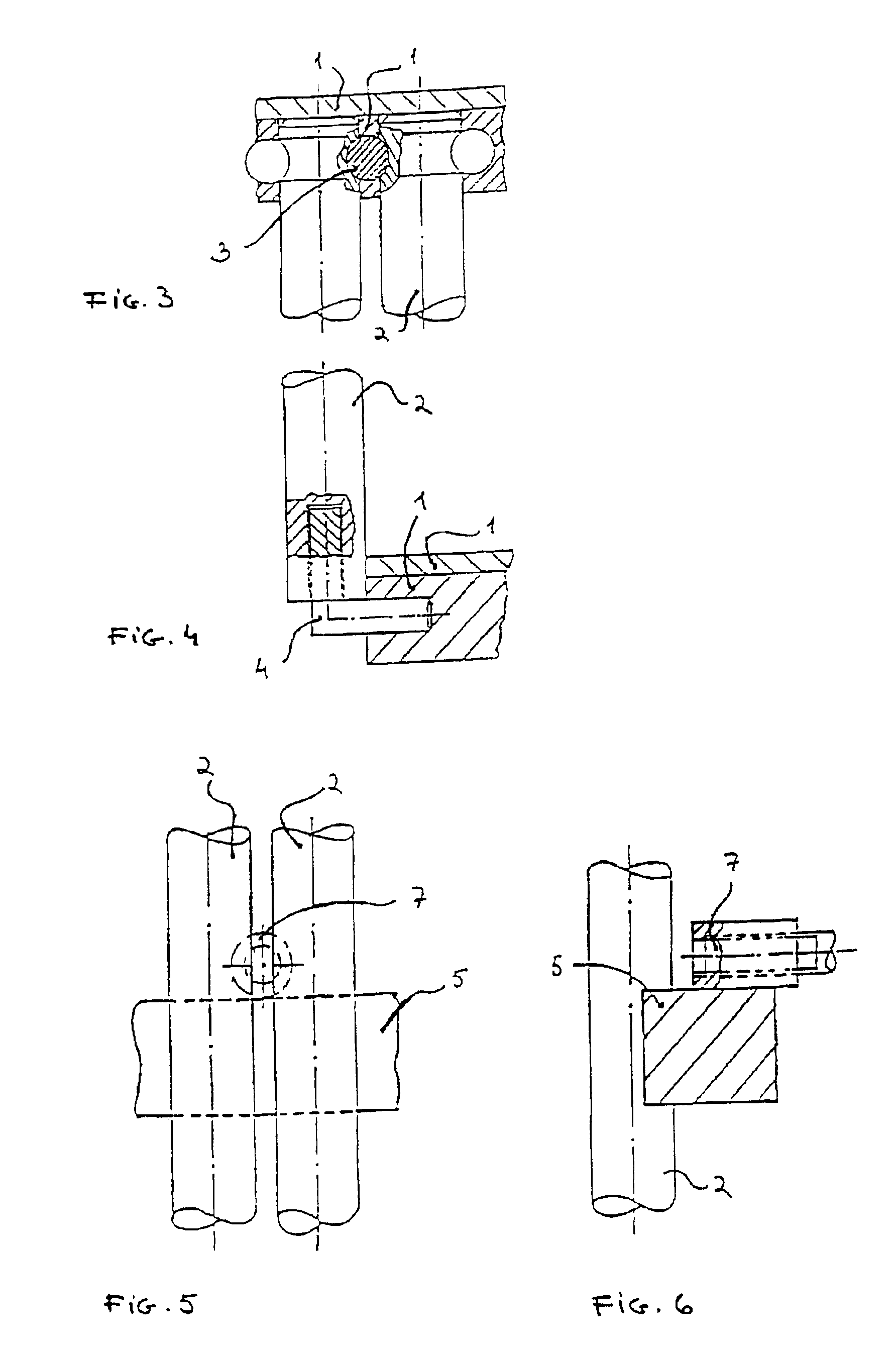
[0038]FIGS. 1 to 6 show a preferred construction of a bar screen to be arranged in a pressure vessel used in making chemical pulp or paper pulp, the bar screen comprising a frame 1 which is arranged to receive an optional number of screen bars 2 which are symmetrical in cross-profile, e.g. round or elliptic. These screen bars are arranged in the frame substantially parallel and side by side. Thus, the screen bars are at one-top-end connected to the frame by a cottered joint 3 as shown in FIG. 3 or by another corresponding method to avoid welding and the damage it causes to the coating, for instance. Correspondingly, the opposing-lower-ends of the screen bars are, for the same reason, arranged to the f...


PUM


Abstract

A bar screen is primarily intended for use in draining liquid from wood chips and pulp without blocking the bar screen. The area of use is especially a process area, in which cooking and circulation liquid is removed from a pressure vessel when making chemical pulp and paper pulp by continuous method. This type of bar screen is characterized in that behind the filtering gap of the screen bars, there is a flow space in which the liquid flows towards a discharge outlet. By adjusting the flow space, a flow rate of liquid which stops blocking due to accumulation is maintained in the background. The sturdiness of the screen structure is improved by adjustable support taps.

Description

FIELD OF THE INVENTION[0001]The present invention relates to a bar screen primarily used to drain liquid from wood chips and / or pulp. The area of use is then the removal of cooking and circulation liquid in particular from a pressure vessel during the preparation of chemical pulp or paper pulp in a continuous method or batch cooking method.BACKGROUND OF THE INVENTION[0002]Today, both strength and a low kappa number, i.e. a low lignin content after cooking, are both required of chemically prepared pulp. The requirements are in conflict unless cooking conditions are carefully optimized. These cooking conditions include a correct alkali split, a suitable temperature profile, an adequate amount of liquid, and as small gradients as possible especially in the radial direction of a continuous digester. This requires high circulation and expansion flows.[0003]Because even a partial blocking of expansion and circulation screens causes channelling and disturbed flows in the digester, and ofte...

Claims


Application Information

Patent Timeline
IPC IPC(8): D21C7/00D21C7/14
CPCD21C7/14D21C7/00
Inventor ISOLA, ANTTI
Owner VALMET TECH INC
Why Eureka
Try Eureka