Coupon dispenser device

a dispenser device and coupon technology, applied in the direction of instruments, machines for issuing preprinted tickets, de-stacking articles, etc., can solve the problems of prone to failure, inability to ensure repeatable individual delivery of coupons, etc., and achieve the effect of convenient consumer retrieval and removal, reliable dispensing operation, and convenient access

Inactive Publication Date: 2005-05-10
FLOORGRAPHICS
View PDF23 Cites 10 Cited by
  • Summary
  • Abstract
  • Description
  • Claims
  • Application Information

AI Technical Summary

Benefits of technology

[0005]A more particular object of the present invention is to provide and improved coupon dispensing device that holds a stack of coupons in a specially structured internal arrangement for a more consistent distribution and positive discharge of the coupons sequentially throughout the device.
[0006]Another object of the present invention is to provide a coupon dispenser device that provides a repeatable discharge and individual delivery of coupons in a form that is accessible and easy for the consumer to retrieve and remove.
[0007]Still another object of the present invention is to provide a coupon dispenser device that is reliable in its dispensing operation and made to resist jamming of the coupons contained therein.
[0008]A still further object of the present invention is to provide a reliable coupon dispenser device that is easy to make and assemble, readily mounted to store shelves and adaptable to a variety of specialized promotions.

Problems solved by technology

While the variety of pre-existing coupon dispensers and their associated interfolded coupon stacks have been generally satisfactory, they have not proven to ensure a repeatable individual delivery of coupons, regardless of their size and shape, in a retrieval manner that is easily accessible for the consumer.
Although electrically powered coupon dispensing devices have proven capable of the repetitive delivery of the coupons in sequence, they are prone to failure due to their power requirements and complex mechanizations.

Method used


Image

  • Coupon dispenser device
  • Coupon dispenser device
  • Coupon dispenser device

Examples


Embodiment Construction

[0020]The following is a detailed description of a preferred embodiment of the present invention and the best presently contemplated mode of its production and practice. This description is further made for the purpose of illustrating the general principles of the invention but should not be taken in a limiting sense, the scope of the invention being best determined by reference to the appended claims.

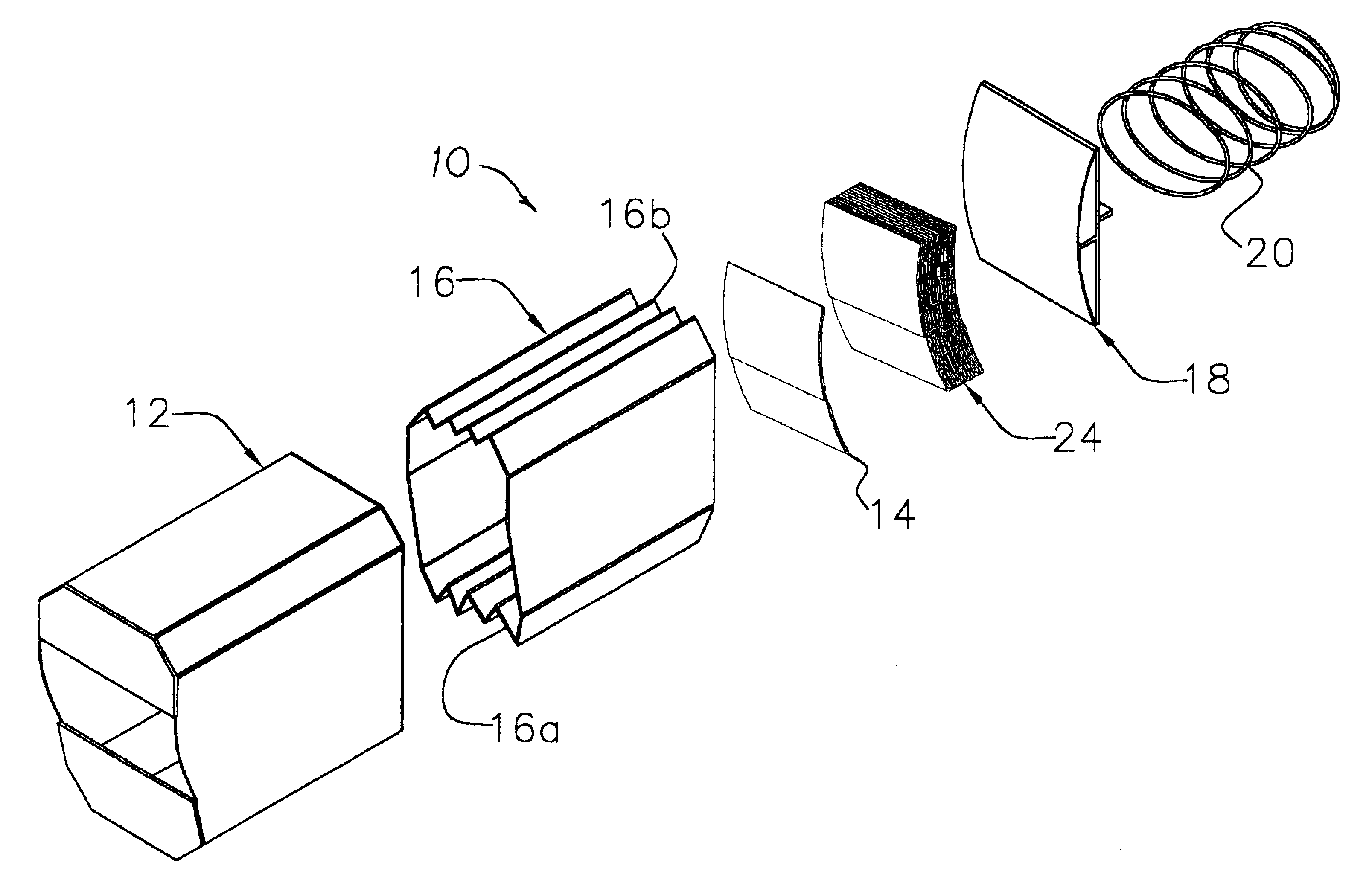
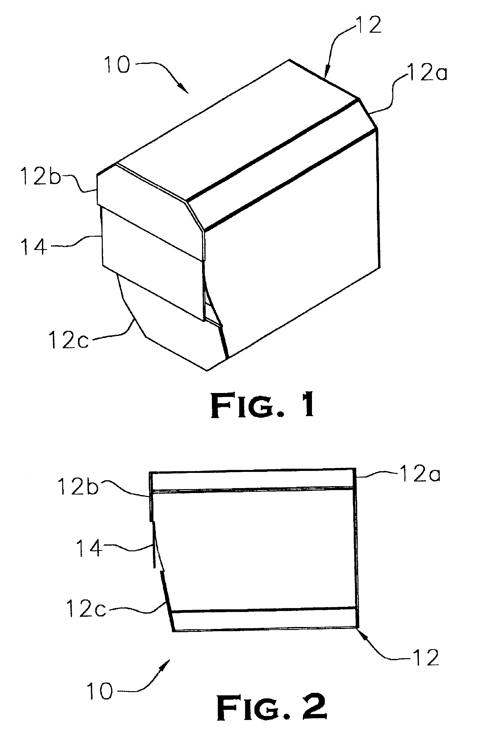
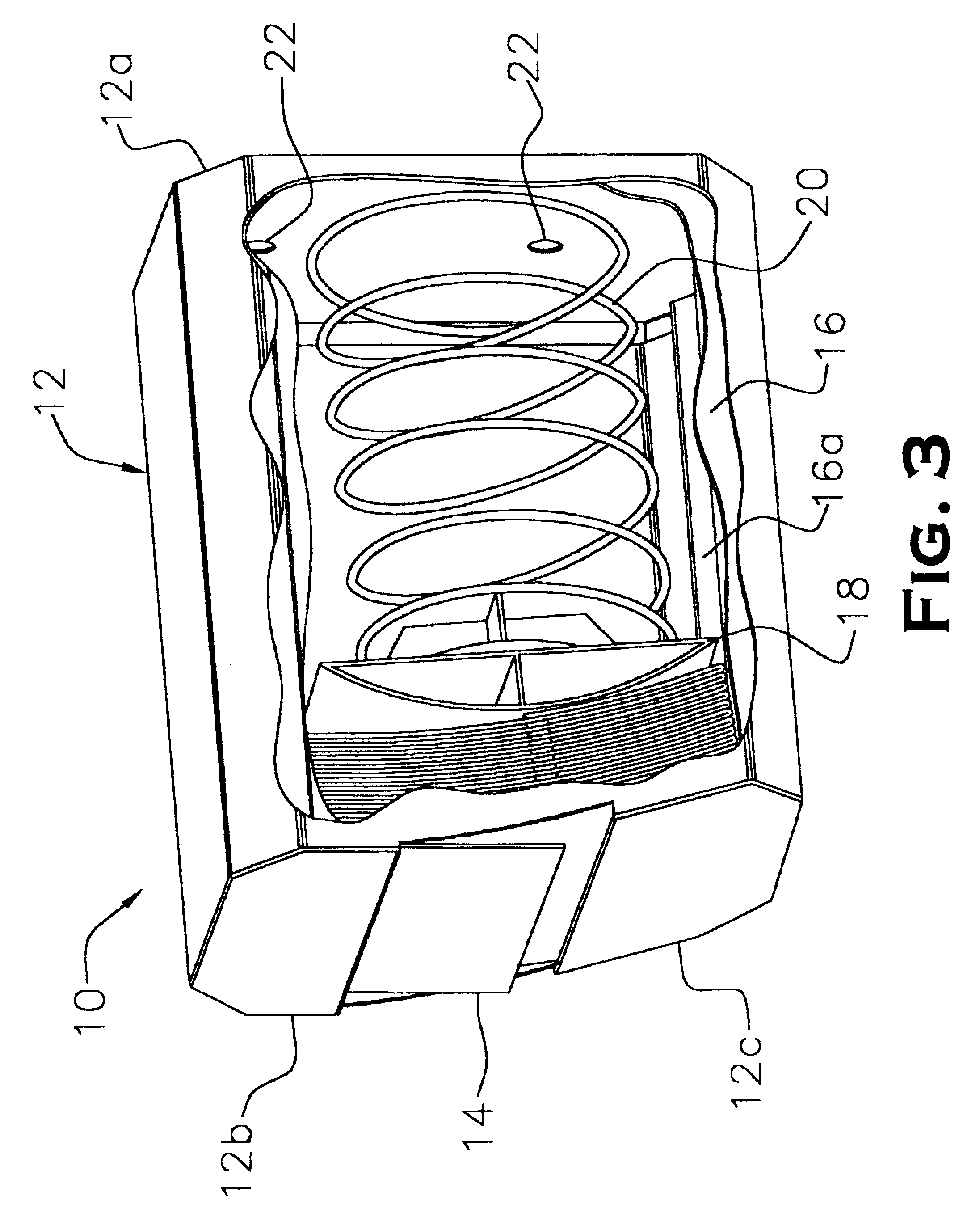
[0021]Referring now to the drawings and particularly at first FIGS. 1 and 2, the coupon dispenser device of the present invention, generally designated 10, is shown assembled and ready to deliver a coupon sheet 14 or like piece of promotional material for retrieval by a consumer. The exterior of the coupon dispenser device 10 comprises an outer box 12 having top, bottom, back and side walls substantially normal to each other. Made from a stiff, relatively thick paper material, preferably cardboard, the outer box 12 is further formed having flattened sections 12a connecting the top, bot...


PUM


Abstract

An improved coupon dispenser device is disclosed comprising an outer box having a sloped front end with rectangular opening therein, a channeled inner sleeve longitudinally extending through the outer box, and a curved, spring-loaded pusher member therein contained and directed to urge a stack of folded coupon sheets axially through the sleeve and to the opening in the outer box in a deflected manner. The inner sleeve is constructed having channeled top and bottom wall surfaces substantially saw-tooth in their configuration and further formed having a sloped profile at its open front end conforming with the sloped front end of the outer box. The sloped front end of the outer box is formed in two divergent planes established by separate top and bottom panels positioned on either side of the opening so that the outermost coupon sheet is delivered at the opening with its leading flap extending therefrom in a position of easy retrieval for the consumer. The coupon dispenser device may be mounted upon a store shelf or other like surface using conventional means.

Description

BACKGROUND OF THE INVENTION[0001]The present invention relates to devices for delivering retail promotions, such as product or price coupons, in the form of individual sheets of paper to a consumer at a point-of-purchase, and more particularly to a coupon dispensing device wherein a specially configured outer box having a sloped front end set in two divergent planes and a channeled inner sleeve extending longitudinally through the outer box are combined with a spring-loaded pusher member to improve distribution and delivery of a stack of folded coupons stored within the device.[0002]In the field of retail marketing and store promotions, the use of coupon dispensers is widespread particularly at the point of consumer selection and purchase of the product. Often mounted on retail shelves in proximity to the associated product, these coupon dispensers have traditionally been mechanical or electro-mechanical in their operation and have been designed in a variety of configurations to del...

Claims


Application Information

Patent Timeline
Patent Type & Authority Patents(United States)
IPC IPC(8): B65D83/08B65D83/12G07B5/00G07B5/02G07B3/00G07B3/04
CPCB65D83/12G07B5/02G07B3/04
Inventor MAGID, EDWARD
Owner FLOORGRAPHICS
Why Eureka
Try Eureka