Temperature measuring sensor incorporated in semiconductor substrate, and semiconductor device containing such temperature measuring sensor

Active Publication Date: 2005-05-10
RENESAS ELECTRONICS CORP
View PDF8 Cites 57 Cited by
  • Summary
  • Abstract
  • Description
  • Claims
  • Application Information

AI Technical Summary

Benefits of technology

[0007]Therefore, a main object of the present invention is to provide a temperature measuring sensor, incorporated in a substrate of a semiconductor device, which is co

Problems solved by technology

In general, a semiconductor device, such as a central processing unit, a microprocessing unit, a digital signal processor or the like, has a large consumption of current, and thereby generates a large amount of heat in operation.
Thus, when the semiconductor device is operated in a high temperature environment, it has a tendency to increase

Method used


Image

  • Temperature measuring sensor incorporated in semiconductor substrate, and semiconductor device containing such temperature measuring sensor
  • Temperature measuring sensor incorporated in semiconductor substrate, and semiconductor device containing such temperature measuring sensor
  • Temperature measuring sensor incorporated in semiconductor substrate, and semiconductor device containing such temperature measuring sensor

Examples


first embodiment

[0069]FIG. 5 shows a semiconductor device according to the present invention, which is generally indicated by reference 30. The semiconductor device 30 comprises a silicon substrate 32, and a main circuit section 34 defined on the silicon substrate 32, and the main circuit section 34 includes various circuits which are arranged so that the semiconductor device 30 functions as a central processing unit, a microprocessing unit, a digital signal processor or the like.

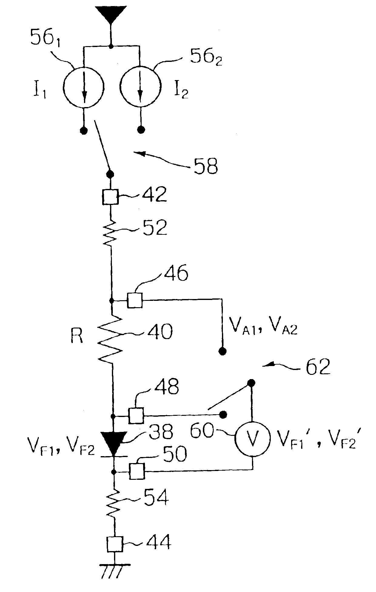
[0070]As shown in FIG. 5, the semiconductor device 30 contains a temperature measuring sensor 36 incorporated therein. Namely, the temperature measuring sensor 36 comprises a p-n junction diode 38 formed in the silicon substrate 32, a resistor 40 formed in the silicon substrate 32 and connected to the diode 38 in series, and first, second, third, fourth, and fifth electrode pads 42, 44, 46, 48, and 50 formed on the silicon substrate 32 and associated with the diode 38 and the resistor 40.

[0071]In particular, an anode termi...

second embodiment

[0119]In this second embodiment, the semiconductor device 74 contains an internal temperature management system, which includes a temperature measuring sensor 80 and a temperature calibration circuit 82 associated with each other and provided in the main circuit section 78. The semiconductor device 74 further contains an additional temperature measuring sensor 84 formed in the silicon substrate 76 in the vicinity of the temperature measuring sensor 80. As shown in FIG. 11, although the additional temperature measuring sensor 84 is disposed at a margin area of the silicon substrate 76, it may be provided in the main circuit section 78, if necessary.

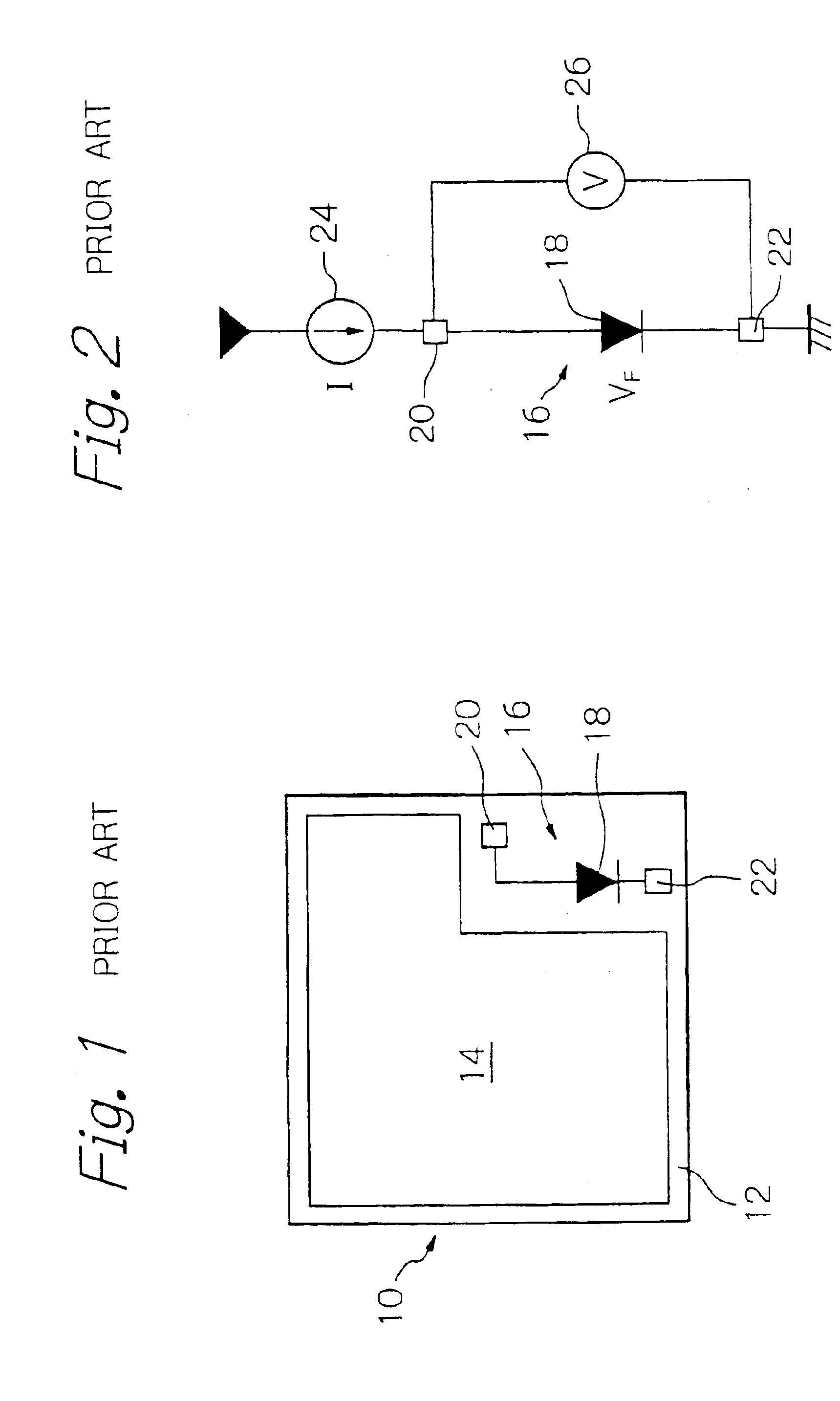
[0120]As is apparent from FIG. 12, the temperature measuring sensor 80 is constituted as a conventional type of temperature measuring sensor, as shown in FIGS. 1 and 2. Namely, the temperature measuring sensor 80 comprises a p-n junction diode 80A formed in the silicon substrate 76, and a constant current source 80B for supplying a constan...


PUM


Abstract

A temperature measuring sensor is incorporated in a substrate of a semiconductor device and has a diode, and resistor formed in the substrate and connected in series. When a first forward constant current is supplied to the diode through the resistor, a potential difference VA1 is produced between terminal ends of both the diode and the resistor, and a potential difference VF1 is produced between terminal ends of the diode. When a second forward constant current is supplied to the diode through the resistor, a potential difference VA2 is produced between the terminal ends of both the diode and the resistor, and a potential difference VF2 is produced between the terminal ends of the diode. A real temperature T of the substrate is calculated by the following formula:
T=(q/k)(VF1−VF2)[1/[ln((VA1−VF1)/(VA2−VF2))]]
herein: T is an absolute temperature, k is Boltzmann's constant, and q is an electron charge.

Description

BACKGROUND OF THE INVENTION[0001]1. Field of the Invention[0002]The present invention relates to a temperature measuring sensor incorporated in a semiconductor substrate to measure a temperature of the semiconductor substrate. Also, the present invention relates to a semiconductor device containing a temperature measuring sensor which is incorporated in a substrate of the semiconductor device to thereby measure a temperature of the semiconductor device. Further, the present invention is relates to a temperature measurement method using the temperature measuring sensor, and various systems using the temperature measuring sensor.[0003]2. Description of the Related Art[0004]In general, a semiconductor device, such as a central processing unit, a microprocessing unit, a digital signal processor or the like, has a large consumption of current, and thereby generates a large amount of heat in operation. Thus, when the semiconductor device is operated in a high temperature environment, it h...

Claims


Application Information

Patent Timeline
IPC IPC(8): G01K7/01H01L21/66H01L21/822H01L27/04
CPCG01K7/01G01K15/005
Inventor TANAKA, NOBUE
Owner RENESAS ELECTRONICS CORP
Why Eureka
Try Eureka