
Dried product discharge system

a technology for discharging systems and dried products, which is applied in drying, lighting and heating apparatus, and stationary filter elements. it can solve the problems of difficult to meet the overall dimensions of the device, high costs, etc., and achieve the effect of simplifying the entire structure of the container, facilitating the external discharge of the product, and reducing costs

Inactive Publication Date: 2005-05-10
3V COGEIM
View PDF19 Cites 52 Cited by
  • Summary
  • Abstract
  • Description
  • Claims
  • Application Information

AI Technical Summary

Benefits of technology

[0007]The aim of the present invention is to solve the above mentioned drawbacks by providing a system for discharging dried product, particularly for drying filters, drying units and the like, that allows to facilitate the external discharge of the product without having to resort to a hatch-type opening, as instead occurs in the prior art, thus simplifying considerably the entire structure of the container and consequently reducing costs.
[0008]Within this aim, an object of the invention is to provide a discharge system and method that allow to achieve an optimum product discharging, with the advantage of being able to adjust and meter at will the discharged quantity, since the opening and closure of a hatch is eliminated completely.
[0009]Another object of the present invention is to provide a discharge system that simplifies considerably all the cleaning and sealing operations, since the hatch remains completely unused.
[0010]Another object of the present invention is to provide a discharge system that thanks to its particular constructive characteristics is capable of giving the greatest assurances of reliability and safety in use.
[0011]Another object of the present invention is to provide a system for discharging dried product, particularly for drying filters, drying units and the like, that can be obtained easily starting from commonly commercially available elements and materials and is furthermore competitive from a merely economical standpoint.

Problems solved by technology

To perform cleaning, it is necessary to resort to particular precautions, such as the use of glove boxes, which are expensive, or of other systems for protecting the operator or the environment, which involve very high costs and increased overall dimensions of the device that are difficult to meet.
Moreover, another problem that can be observed with the discharge systems of the prior art consists in that the hatches that are currently used do not allow to perform a metered discharge, since they simply allow opening or closure, with consequent escape of the product without the possibility to regulate the quantity.

Method used


Image

  • Dried product discharge system
  • Dried product discharge system
  • Dried product discharge system

Examples


Embodiment Construction

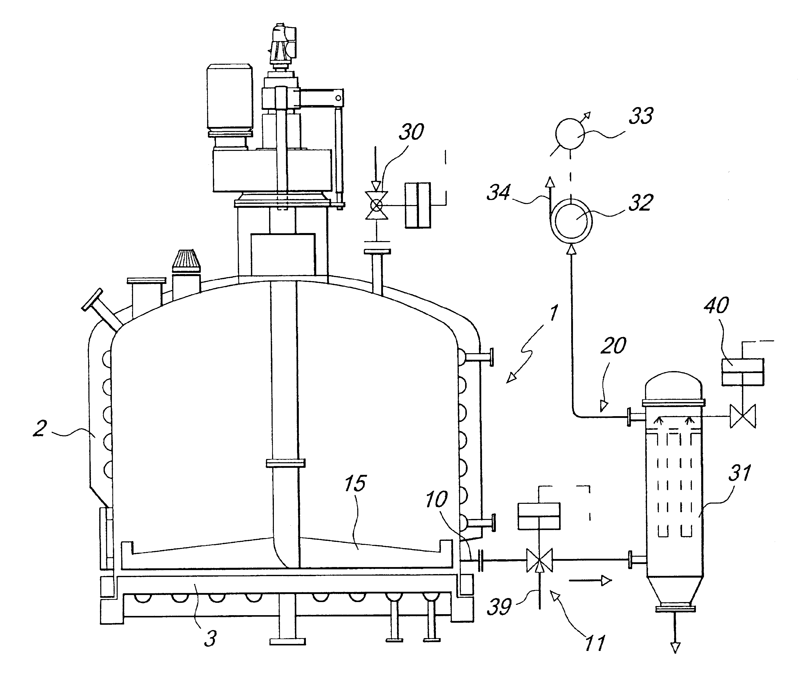
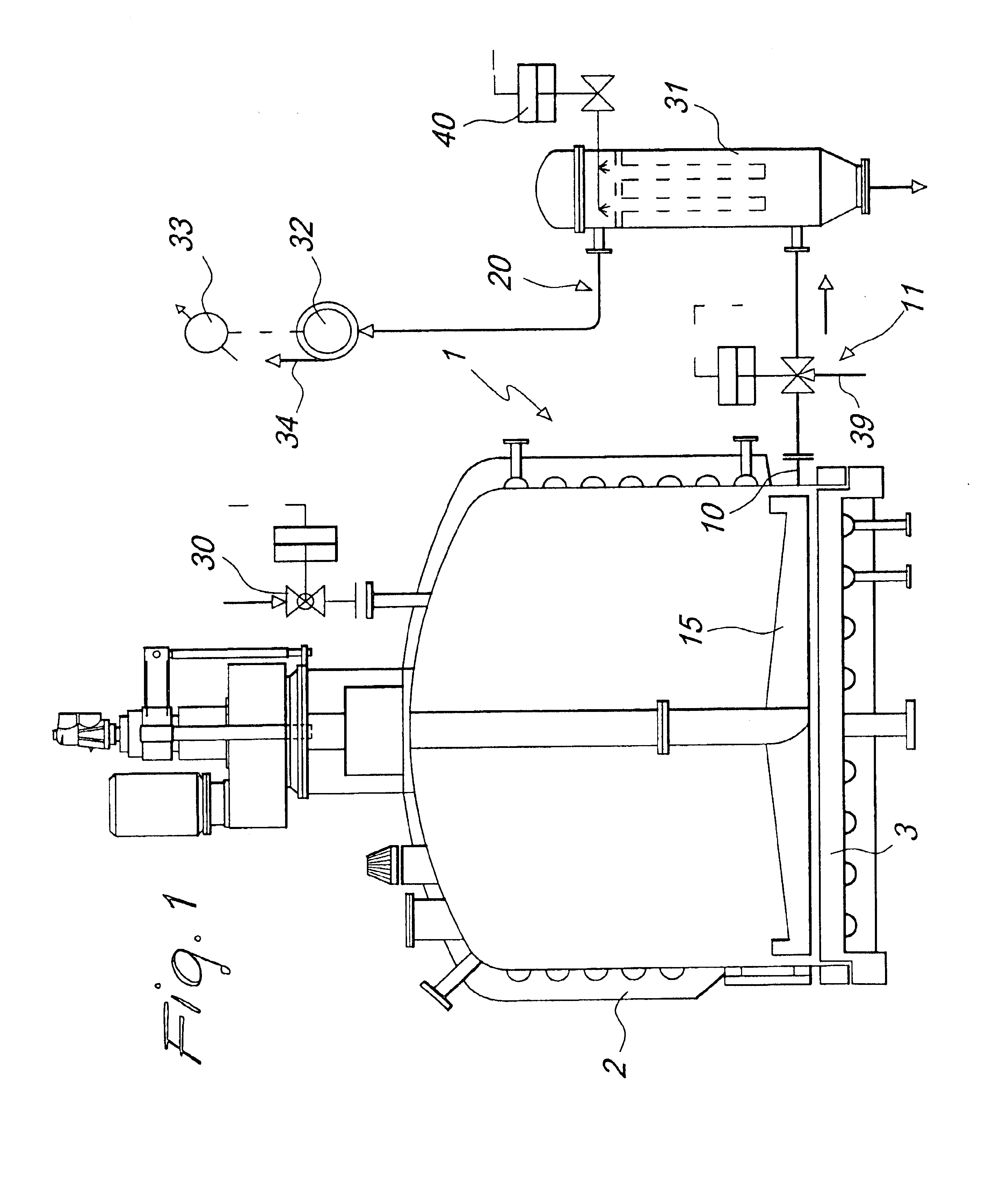
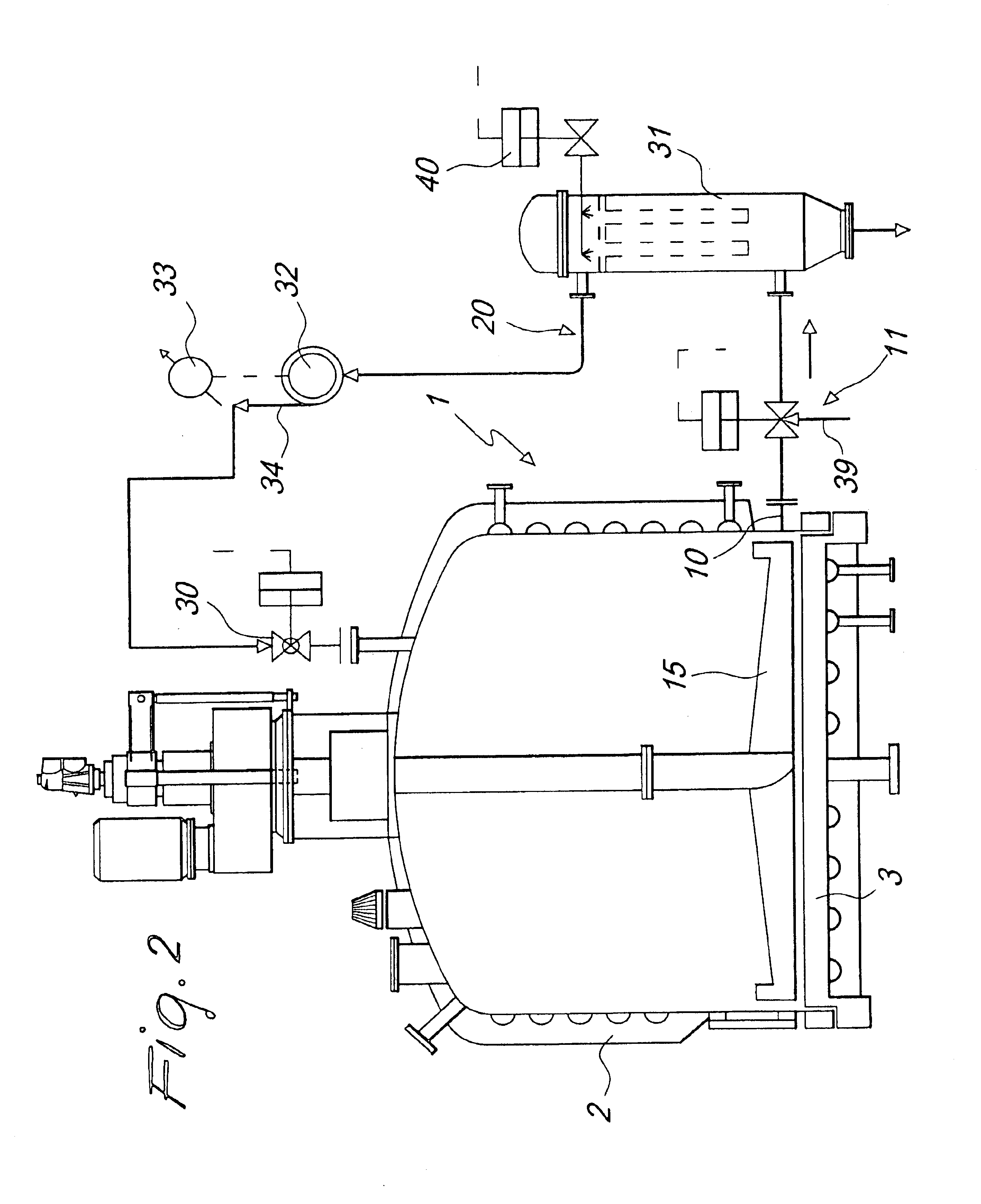
[0017]With reference to the figure, a container for treating and containing a dried product is shown and is generally designated by the reference numeral 1; in a per se known manner, the container is formed by an upper body 2 closed by a bottom 3 where the usual filtering mesh 4 is optionally provided.

[0018]The particularity of the invention consists in that there is a discharge hole 10 controlled by a discharge valve 11, which is interposed on a pneumatic circuit 20 that produces a circulation of fluid inside the container 1, so as to convey externally the dried product, which is stirred and moved by means of a conventional agitator 15 arranged inside the container.

[0019]The discharge hole, as shown in the drawing, is located proximate to the bottom; its location can of course be defined depending on the various operating requirements.

[0020]The invention has the aim of avoiding the use of the conventional hatch, which might be provided but not used, in the case of a container that ...


PUM


Abstract

A system for discharging dried product, particularly for drying filters, drying units and the like, comprising, on a container for treating and containing a dried product, a discharge hole that is controlled by a discharge valve, interposed on a pneumatic circuit suitable to produce a circulation of fluid in output from the discharge hole. An agitator is also provided which acts on the dried product to facilitate its outward conveyance.

Description

BACKGROUND OF THE INVENTION[0001]The present invention relates to a system for discharging dried product, particularly for drying filters, drying units and the like.[0002]It is known that drying filters are generally structurally constituted by a container in which a solid portion is separated from a liquid in a closed chamber that can optionally be pressurized; the separated portion is thereafter subjected to streams of hot air and / or to heating from the chamber walls and to stirring from an agitator, so as to eventually dry the product within the same system.[0003]These drying filters have, in their lower part, a discharge hatch that is arranged either laterally or on the bottom thereof, is of the plug or swinging type, and can be opened for discharging the product that has to be transferred externally.[0004]In order to achieve a good seal, discharge hatches are provided with an O-ring seal or a metal-to-metal seal that is particularly critical in operation, especially after disch...

Claims


Application Information

Patent Timeline
IPC IPC(8): B01D29/01F26B11/14F26B11/00F26B25/00
CPCB01D29/01F26B11/14F26B25/002F26B25/007B01D29/843B01D29/86
Inventor FABBRI, LUIGI
Owner 3V COGEIM
Learn More