
Electrical connector

a technology of electrical connectors and connectors, applied in the direction of coupling device connections, coupling protective earth/shielding arrangements, electrical devices, etc., can solve the objectionable limitation of information transmission speed, and achieve the effect of improving the shielding effect and sufficient high-speed information transmission

Inactive Publication Date: 2005-05-10
DDK LTD
View PDF3 Cites 21 Cited by
  • Summary
  • Abstract
  • Description
  • Claims
  • Application Information

AI Technical Summary

Benefits of technology

"The invention is an improved electrical connector that solves the problems of previous designs. It has metallized surfaces around the contact insertion apertures, making it more effective at shielding and allowing for faster information transmission. Ground contacts can also be easily grounded or earthed. The invention is particularly useful for high-speed information transmission."

Problems solved by technology

Even with fine or narrow pitches of contacts, however, gaps between the ground contacts become rather wider so that shielding effect could not be sufficiently obtained and hence information transmission speed would be objectionably limited to values of the order of several hundreds mega bits per second.

Method used


Image

  • Electrical connector
  • Electrical connector
  • Electrical connector

Examples


Embodiment Construction

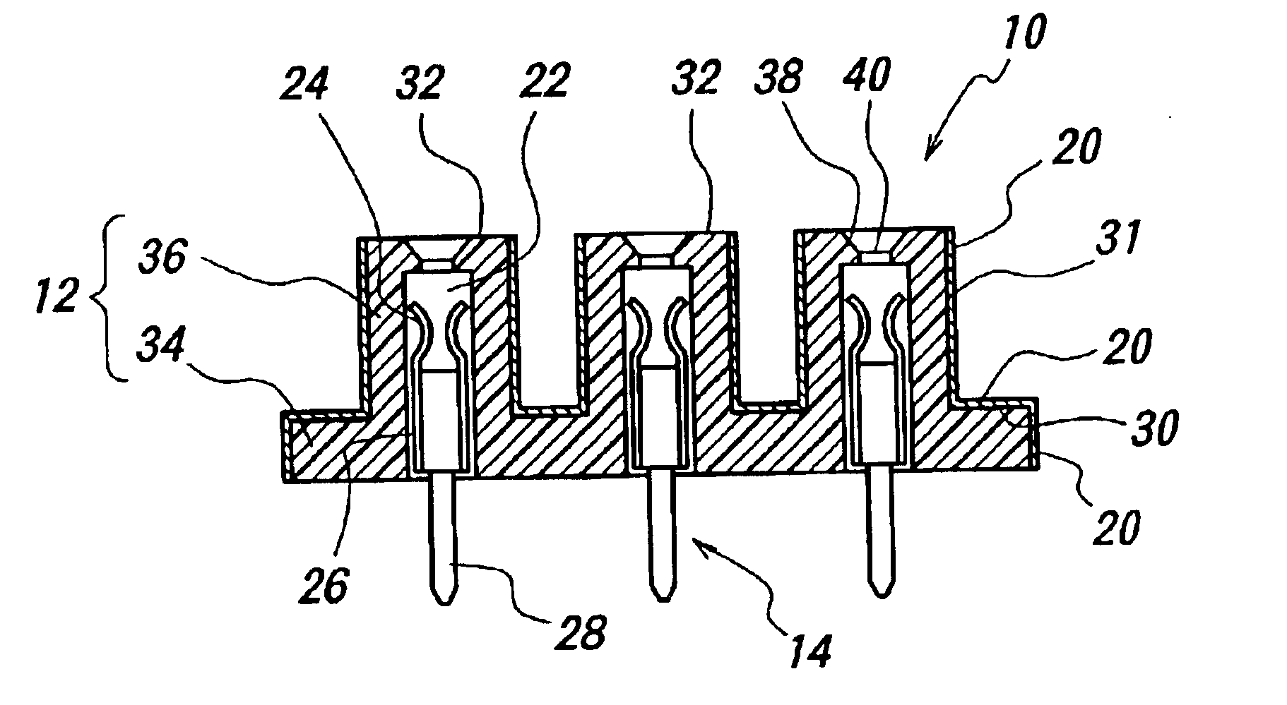
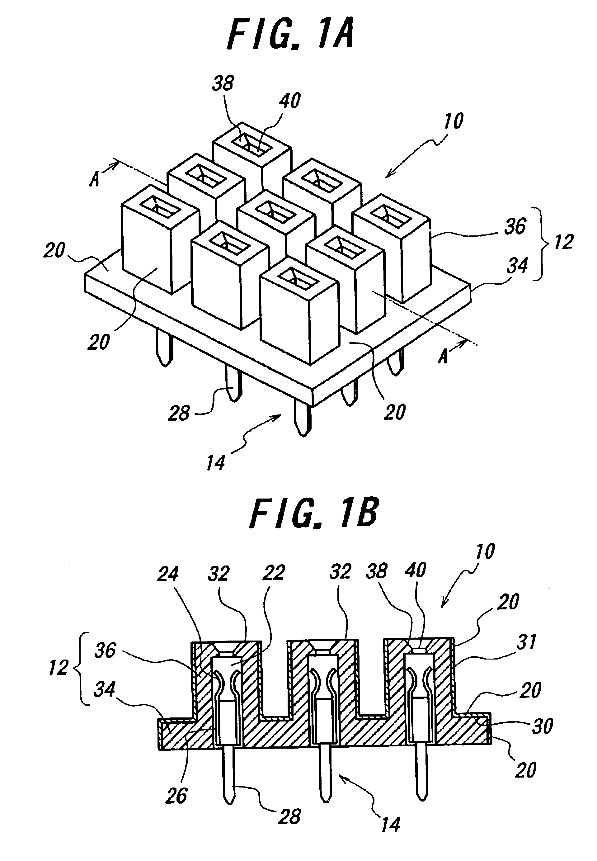
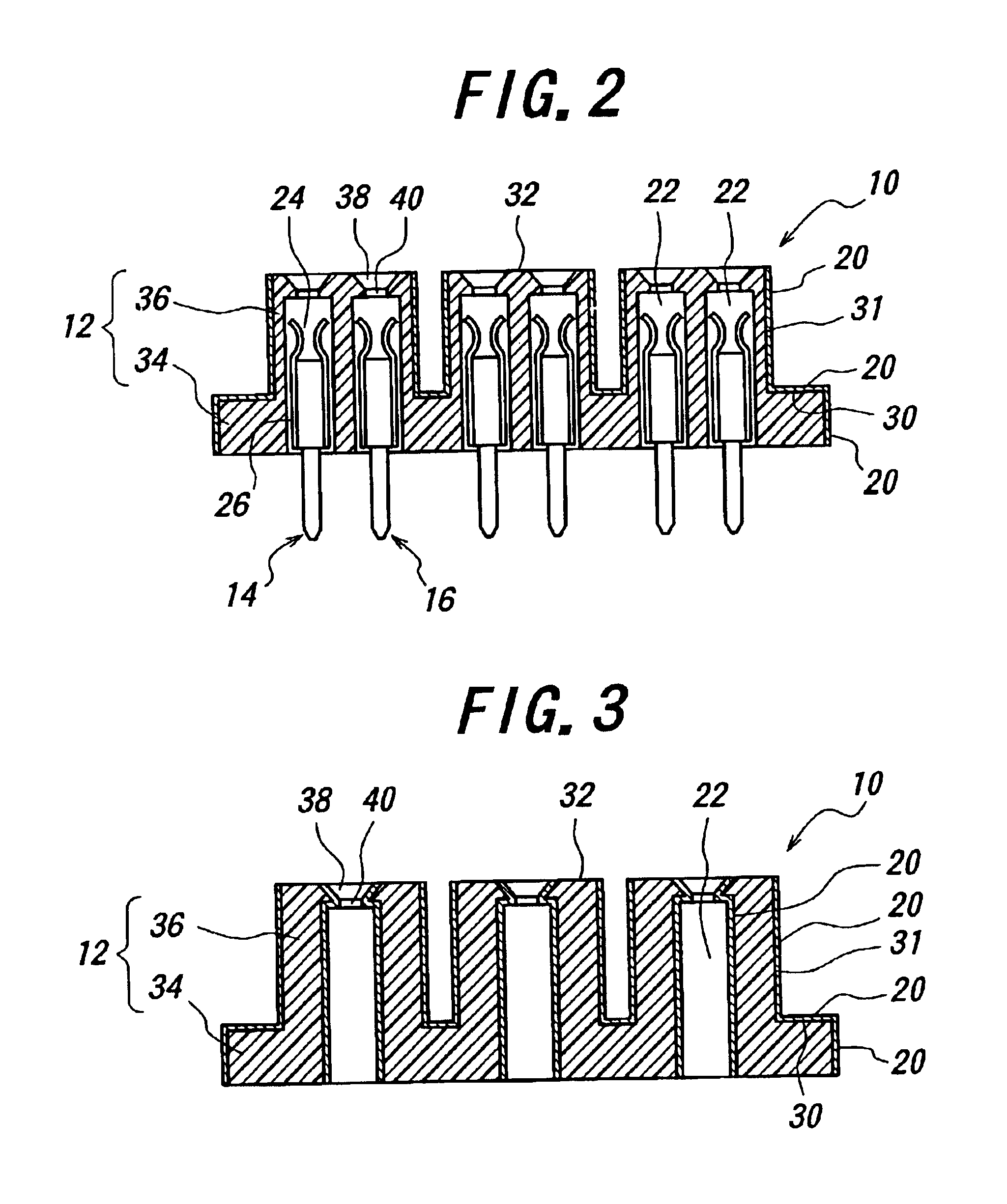
[0021]FIG. 1A illustrates in a perspective view an electrical connector according to the first aspect of the invention whose cross-section is shown in FIG. 1B taken along a plane A—A in FIG. 1A. FIG. 2 illustrates, in a sectional view, metallized projections of the electrical connector each having a pair of contact insertion apertures. FIG. 3 shows contact insertion apertures with metallized inner surfaces. FIG. 4 illustrates metallized projections each having three contact insertion apertures. FIG. 5 shows a cross-section of an electrical connector illustrating a main body and a plurality of metallized projections extending therefrom.

[0022]The electrical connector 10 according to the invention shown in FIG. 1A comprises a plurality of contacts and an insulator 12. The contacts are divided into signal contacts 14 and phase inversion signal contacts 16.

[0023]The insulator 12 is injection molded from an electrically insulating plastic material in the conventional manner. Preferred mat...


PUM


Abstract

An electrical connector includes an insulator and a plurality of contacts supported by the insulator. The insulator formed of an insulating plastic material is formed with a plurality of contact insertion apertures for inserting the contacts. Surfaces of the insulator around the contact insertion apertures are metallized, while the contact insertion apertures are independently electrically insulated. With this arrangement, substantially high shielding effect and sufficiently high speed information transmission are effectively accomplished.

Description

BACKGROUND OF THE INVENTION[0001]This invention relates to an electrical connector for use in electric and electronic appliances and more particularly to an electrical connector improved in shielding to deal with high-speed information transmission.[0002]FIG. 6 partly illustrates a hitherto used electrical connector viewed from a mating connector. Such an electrical connector of the prior art has a substantially rectangular parallelepiped configuration and includes mainly an insulator and contacts fixed thereto. These contacts may be divided into signal contacts (+S1), phase inversion signal contacts (−S1) with an inverted phase, and ground contacts (G). These contacts are arranged in a manner such that the signal contacts and the phase inversion signal contacts are in pairs and these pairs are surrounded by the ground contacts as shown in FIG. 6.[0003]The signal, phase inversion signal and ground contacts are arranged in the insulator in the manner described above in order to impro...

Claims


Application Information

Patent Timeline
Patent Type & Authority Patents(United States)
IPC IPC(8): H01R13/658H01R13/648H01R13/6599
CPCH01R13/6599Y10S439/931
Inventor OHTSUKI, TOMONARI
Owner DDK LTD
Learn More