Fume hood exhaust stack system

a stack system and exhaust air technology, applied in ventilation systems, domestic stoves or ranges, heating types, etc., can solve the problems of increasing fan power consumption, increasing fan power consumption as exhaust air flow decreases, and often requiring stacks to be as short, so as to achieve energy efficient and environmentally sound, constant velocity and momentum

Inactive Publication Date: 2005-05-10
LIU MINGSHENG
View PDF36 Cites 27 Cited by
  • Summary
  • Abstract
  • Description
  • Claims
  • Application Information

AI Technical Summary

Benefits of technology

[0011]It is also an object of the present invention to utilize a programmable controller and variable speed drive to maintain the exhaust pressure at the inlet of the fan at a relatively constant desired level.
[0012]It is another object of the present invention to provide an advanced fume exhaust stack system that utilizes a programmable controller to modulate the outlet area of the exhaust stack to substantially maintain the total pressure at a constant total pressure set point, thereby ensuring that the toxic exhaust discharged from the stack has a relatively constant velocity and momentum sufficient to ensure that the toxic exhaust reaches an environmentally sound elevation.
[0013]It is yet another object of the present invention to provide an advanced fume exhaust stack system that utilizes a programmable controller to modulate the outlet area of the exhaust stack to substantially maintain the exhaust flow rate at a constant-design flow rate, thereby ensuring that the toxic exhaust discharged from the stack has a relatively constant velocity and momentum sufficient to ensure that the toxic exhaust reaches an environmentally sound elevation.
[0014]Accordingly, the present invention provides for an energy efficient and environmentally sound advanced fume hood exhaust stack system and method that

Problems solved by technology

Due to architecture, structural, and economic limitations, however, the stack is often required to be as short as possible.
The fan power consumption under these partial-exhaust high static pressure conditions is often up to 30% greater than the fan power consumed under full exhaust conditions;

Method used


Image

  • Fume hood exhaust stack system
  • Fume hood exhaust stack system
  • Fume hood exhaust stack system

Examples


Embodiment Construction

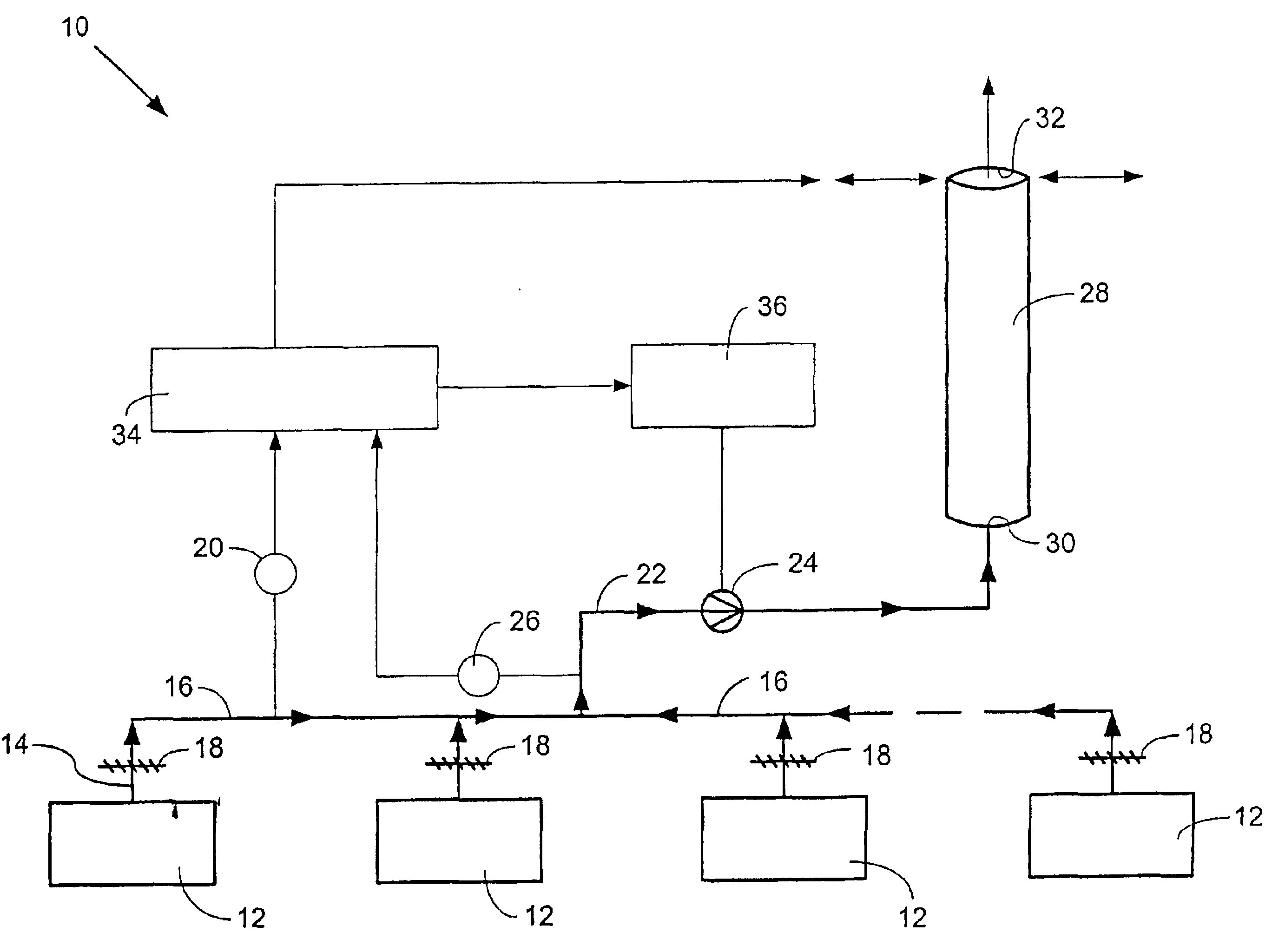
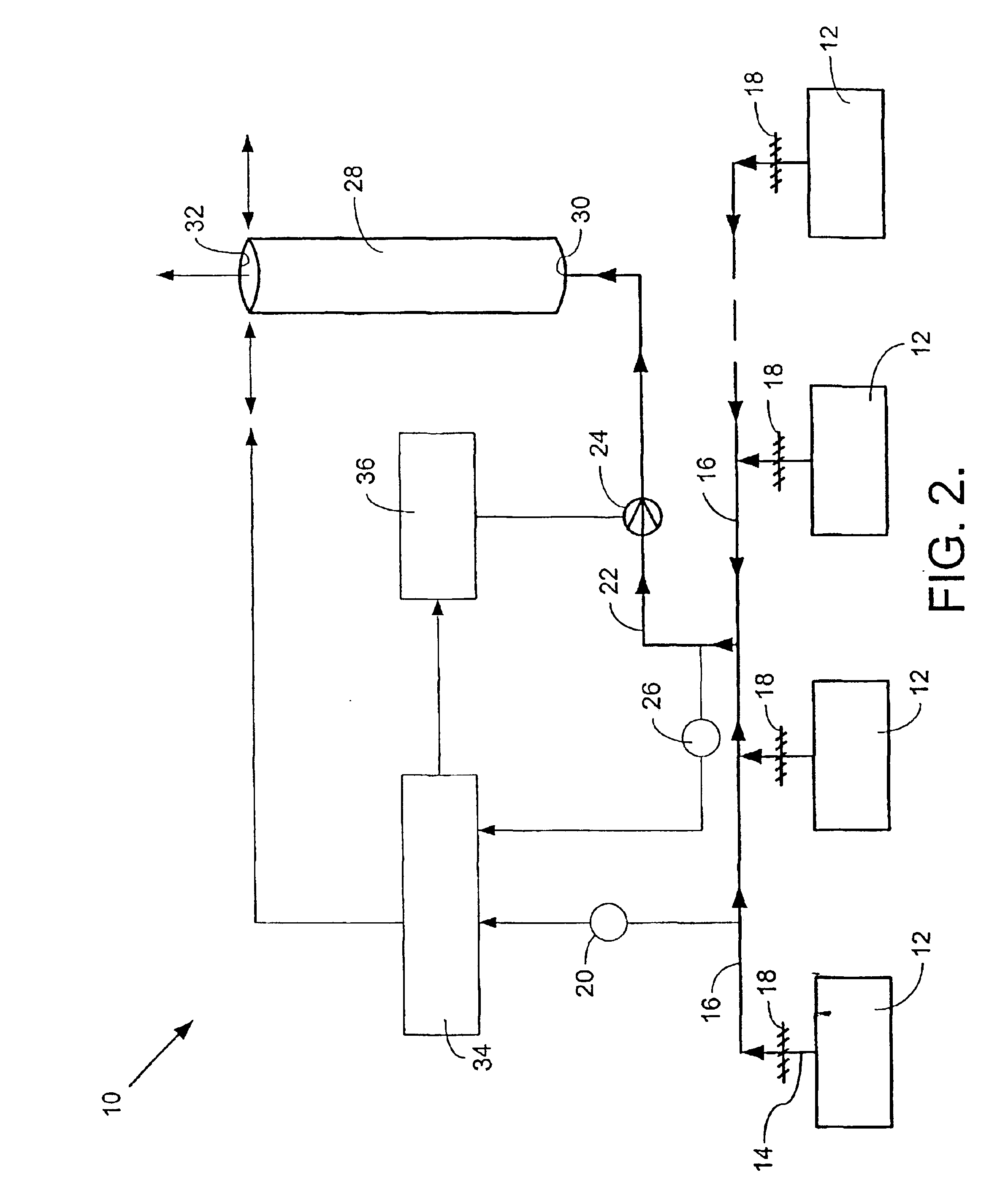
[0019]Referring to the drawings in greater detail, and initially to FIG. 2, an advanced fume hood exhaust stack system is designated generally by the numeral 10. One or more fume hoods 12 collect and discharge toxic exhaust through individual fume hood exhaust conduits 14 and into a common exhaust header 16. Individual fume hood exhaust dampers 18 may be positioned in the individual fume hood exhaust conduits 14, as depicted in FIG. 2, to enable a particular fume hood 12 to be isolated from the system.

[0020]A static pressure sensor and transmitter 20 is located at exhaust header 16 and measures the static pressure of the exhaust within the header 16. The pressure sensor and transmitter 20 is adapted to transmit a signal proportional to the static pressure of the exhaust within the header 16. The proportional transmitter signal may be a pulse signal, a 4-20 mA signal, or other electrical or digital signal commonly employed by and well known to those skilled in the art.

[0021]A header ...


PUM


Abstract

A fume hood exhaust stack system (10) and method utilize a variable speed fan (24) and an exhaust stack (28) having an adjustable cross-sectional area. Toxic exhaust from one or more fume hoods (12) is conveyed through a header (16) to the fan. The fan forces the exhaust through the exhaust stack, and the exhaust is then discharged into the atmosphere at a sufficient velocity and momentum to ensure that the exhaust reaches an environmentally sound altitude. A variable speed drive (36), programmable controller (34), flow signals (26), and static pressure and total pressure signals (20) are utilized to modulate the speed of the fan and the area of the exhaust stack to maintain the desired fan inlet pressure and exhaust velocity.

Description

CROSS-REFERENCE TO RELATED APPLICATIONS[0001]This patent application is a nonprovisional application claiming priority from U.S. provisional application No. 60 / 201,226, filed in the United States Patent and Trademark Office on or about May 1, 2000.STATEMENT REGARDING FEDERALLY SPONSORED RESEARCH OR DEVELOPMENT[0002]Not applicable.BACKGROUND OF THE INVENTION[0003]This invention relates generally to exhaust systems and methods, and more particularly to an energy efficient and environmentally sound advanced stack system and method for exhausting toxic air from fume hoods.[0004]Laboratories and other facilities typically contain fume hoods in which chemical processes produce toxic fumes. These facilities necessarily contain fume exhaust stack systems that exhaust this toxic air from the building and send the toxic air through a stack to a prescribed minimum altitude such that fresh air contamination and environmental pollution is reduced. To satisfy environmental safety standards, the f...

Claims


Application Information

Patent Timeline
IPC IPC(8): B08B15/00B08B15/02F24F7/00
CPCB08B15/002B08B15/023F24F2007/001
Inventor LIU, MINGSHENG
Owner LIU MINGSHENG
Why Eureka
Try Eureka