Ionizing radiation detector and method for manufacturing such a detector

Active Publication Date: 2005-05-10
INSTITUT MAX VON LAUE - PAUL LANGEVIN
View PDF6 Cites 3 Cited by
  • Summary
  • Abstract
  • Description
  • Claims
  • Application Information

AI Technical Summary

Benefits of technology

[0009]An object of the present invention is to provide an assembly which is simple and inexpensive to form of cells sensitive to ionizing radiation.
[0010]Another object of the present invention is to provide such an assembly which has a low maintenance cost.

Problems solved by technology

The forming of such a cell, which implies a perfectly tight welding of plugs 6 under a high pressure, after positioning of the wire, is particularly expensive.
It is possible to provide individual filling means for each cell, but this creates an undesirable additional mechanical bulk.
Further, the uniformity of the cell response is affected by the inaccuracy of the wire centering inside of the tube, and such a wire centering is difficult to perform by means of spring 10.
Now, it is difficult to form several sensitive cells comprising a same gas mixture with a long-term stability and identical for all cells.
As a result, no sensitive cell really has an operation identical to the others.
Further, when several sensitive cells must be used together with a minimum space between the tubes, it is difficult to ensure the continuity of the electromagnetic shielding between the tube envelope and measurement circuit 12 without extending beyond the external diameter of the tube, which results in creating dead spaces between cells, whereby a loss of sensitivity of the assembly.
Further still, a sensitive cell may wear out and need changing, for example, if the gas mixture that it contains has been altered under the influence of the received radiation.
The replacing of a cell is expensive.

Method used


Image

  • Ionizing radiation detector and method for manufacturing such a detector
  • Ionizing radiation detector and method for manufacturing such a detector
  • Ionizing radiation detector and method for manufacturing such a detector

Examples


Embodiment Construction

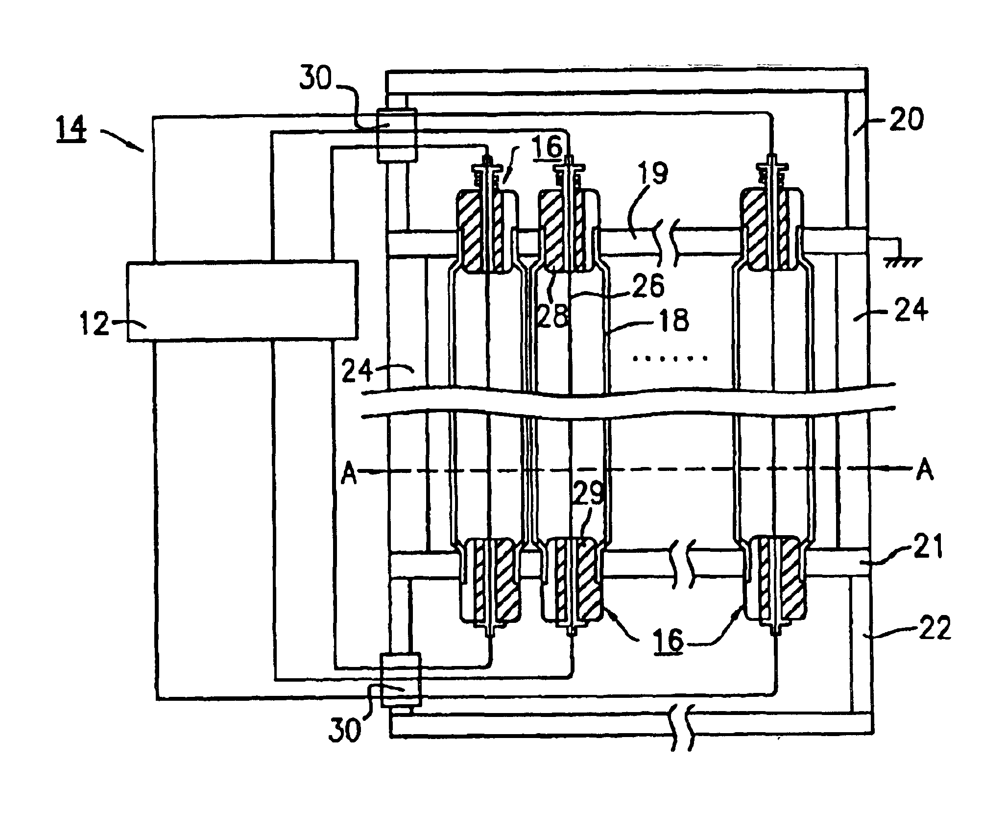
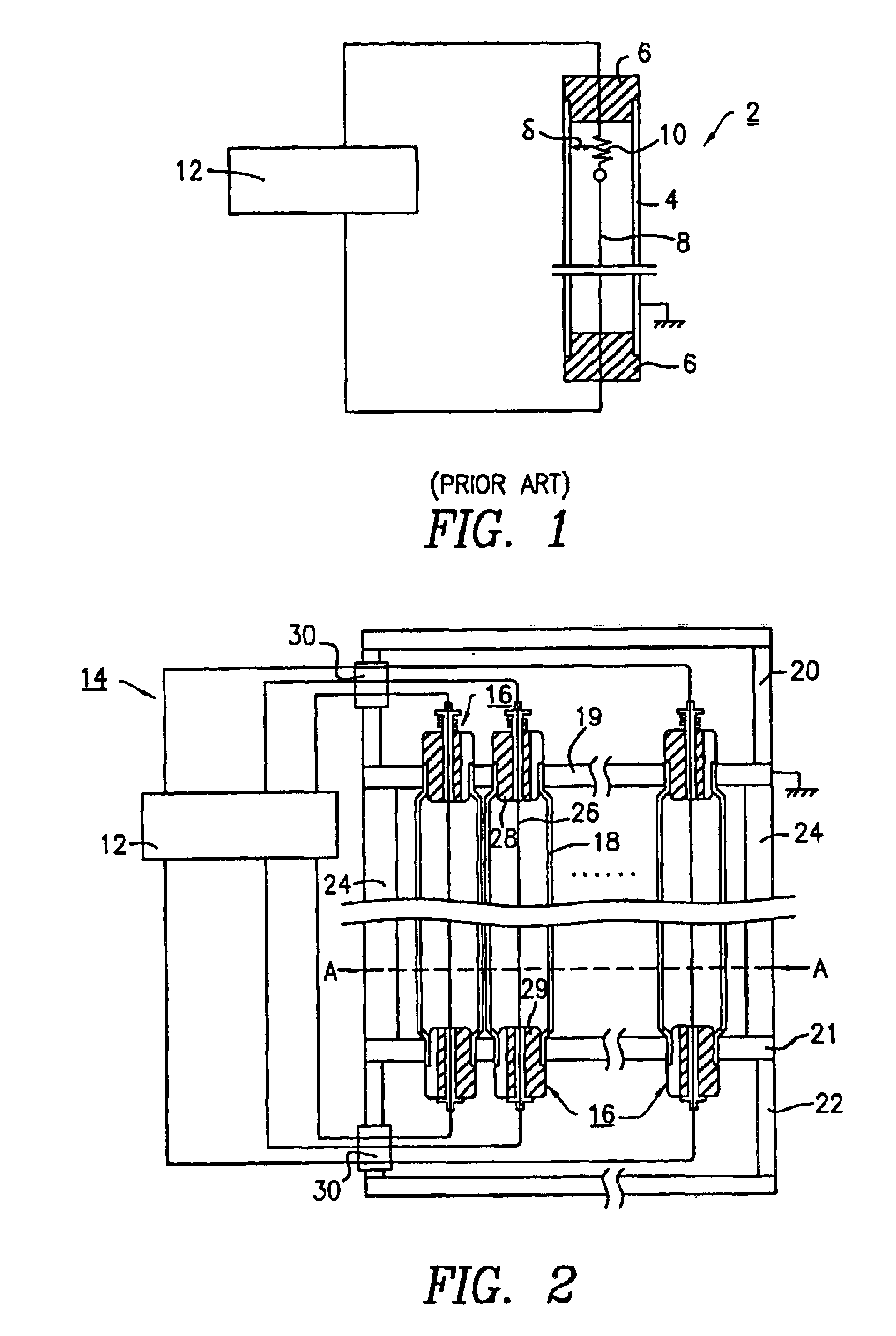
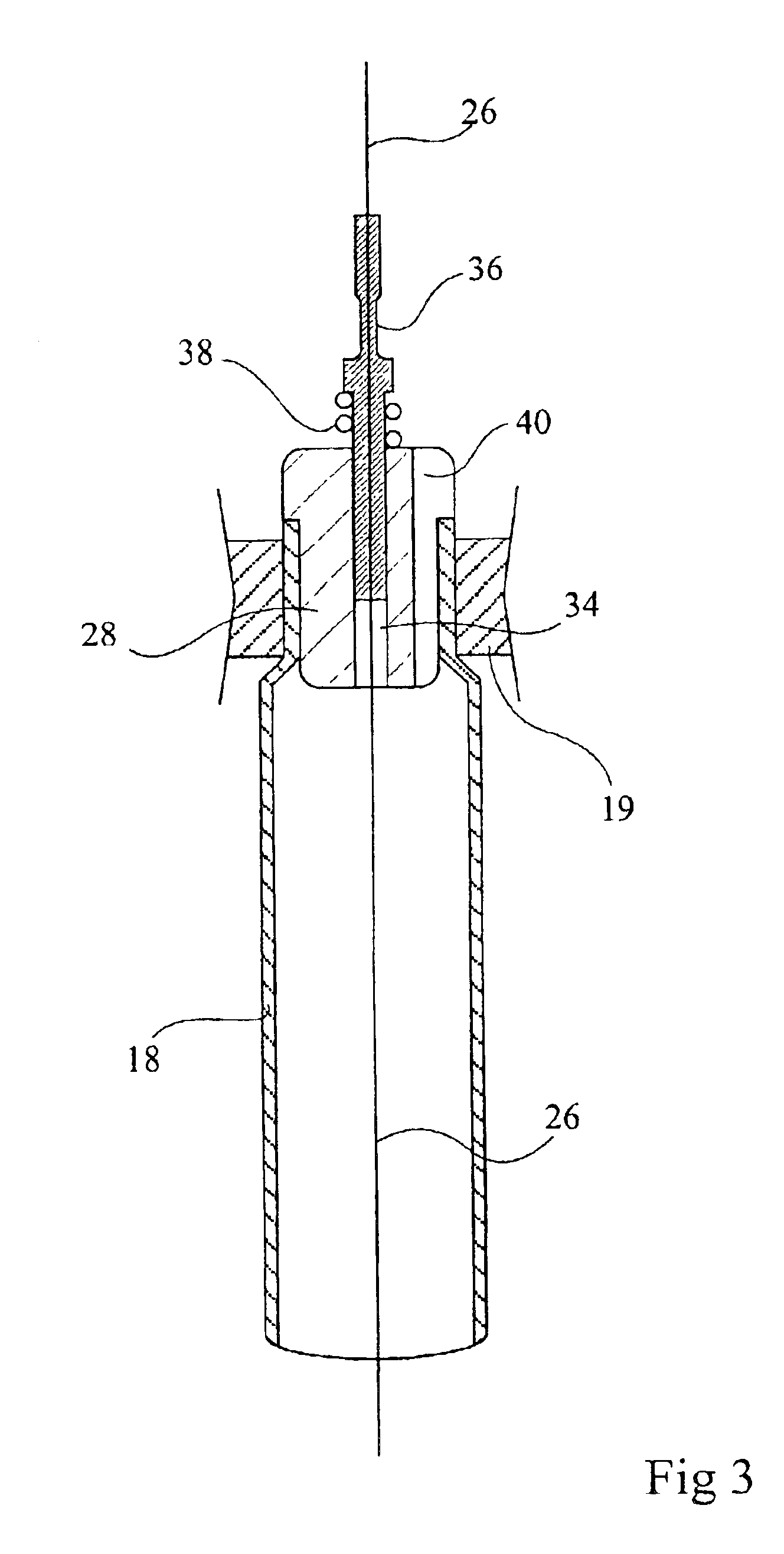
[0028]FIG. 2 schematically shows a detector 14 according to the present invention, comprising a sensitive surface formed of a juxtaposition of tubular sensitive cells 16. Each sensitive cell 16 comprises a conductive tube 18, a first end of which crosses a metallic wall 19 of a tight enclosure 20 and the second end of which crosses a wall 21 of a tight enclosure 22. The ends of tubes 18 are welded to walls 19 and 21 of enclosures 20 and 22 so that the tubes 18 and the enclosures 20 and 22 can be filled together with a single gas mixture under pressure. The ends of tubes 18 have a diameter smaller than the diameter of the tube bulk. The openings of walls 19 and 21 in which are inserted the ends of two adjacent tubes are distant by an interval equal to the difference between the diameter of the ends of the tubes and the tube bulk diameter. This interval between two adjacent openings enables easy welding of the tube ends to walls 19 and 21. Enclosures 20 and 22, formed in a conductive ...


PUM


Abstract

An ionizing radiation detector comprising a plurality of conductive tubes arranged in parallel fashion containing a gas mixture under pressure, a conductive wire being tensed at the center of each tube and adapted to being polarized with respect thereto, and comprising first and second tight enclosures each having a wall provided with openings in which are tightly inserted the first and second ends of each tube, the ends of each tube being open.

Description

BACKGROUND OF THE INVENTION[0001]1. Field of the Invention[0002]The present invention relates to the field of particle or ionizing radiation detectors, and in particular detectors of neutrons, γ- or X-rays.[0003]2. Discussion of the Related Art[0004]FIG. 1 schematically shows the conventional structure of a cell 2 sensitive to an ionizing radiation, using the same detection principle as the present invention. This cell comprises a conductive tube 4 filled with a gas mixture, sealed at its ends by isolating plugs 6. A conductive wire 8, the ends of which tightly cross plugs 6, is maintained tensed at the center of tube 4 by a spring 10 located within the tube. A positive electric voltage applied to wire 8 by means of a measurement circuit 12 enables defining within the tube an electric field which is favorable to the drifting and to the amplification of electrons generated at the passing of the ionizing radiation, which enters the tube in a direction approximately orthogonal to the a...

Claims


Application Information

Patent Timeline
IPC IPC(8): H01J47/02H01J47/00G01T1/185G01T3/00
CPCH01J47/02H01J47/002
Inventor BUFFET, JEAN-CLAUDEGUERARD, BRUNO
Owner INSTITUT MAX VON LAUE - PAUL LANGEVIN
Why Eureka
Try Eureka