High-voltage bidirectional switch

a high-voltage bi-directional switch and switch technology, applied in the direction of basic electric elements, thyristors, electric apparatus, etc., can solve the problems of difficult to form components, large complexity of control circuits, and relatively high cost, and achieve the effect of simple and inexpensive form

Active Publication Date: 2005-07-05
STMICROELECTRONICS SRL
View PDF4 Cites 20 Cited by
  • Summary
  • Abstract
  • Description
  • Claims
  • Application Information

AI Technical Summary

Benefits of technology

[0009]The present invention aims at providing a bidirectional switch that can be triggered by a low-voltage control signal during a halfwave of the supply voltage and remain on until the end of the next halfwave of the supply voltage, which is simple and inexpensive to form.

Problems solved by technology

A disadvantage of such switches is that the control circuit is generally complex and expensive to form.
Further, such a circuit may require use of one or several high-voltage capacitors, which components are difficult to form and are relatively expensive.

Method used


Image

  • High-voltage bidirectional switch
  • High-voltage bidirectional switch
  • High-voltage bidirectional switch

Examples


Embodiment Construction

[0030]For clarity, only those elements that are necessary to the understanding of the present invention have been shown and will be described hereafter.

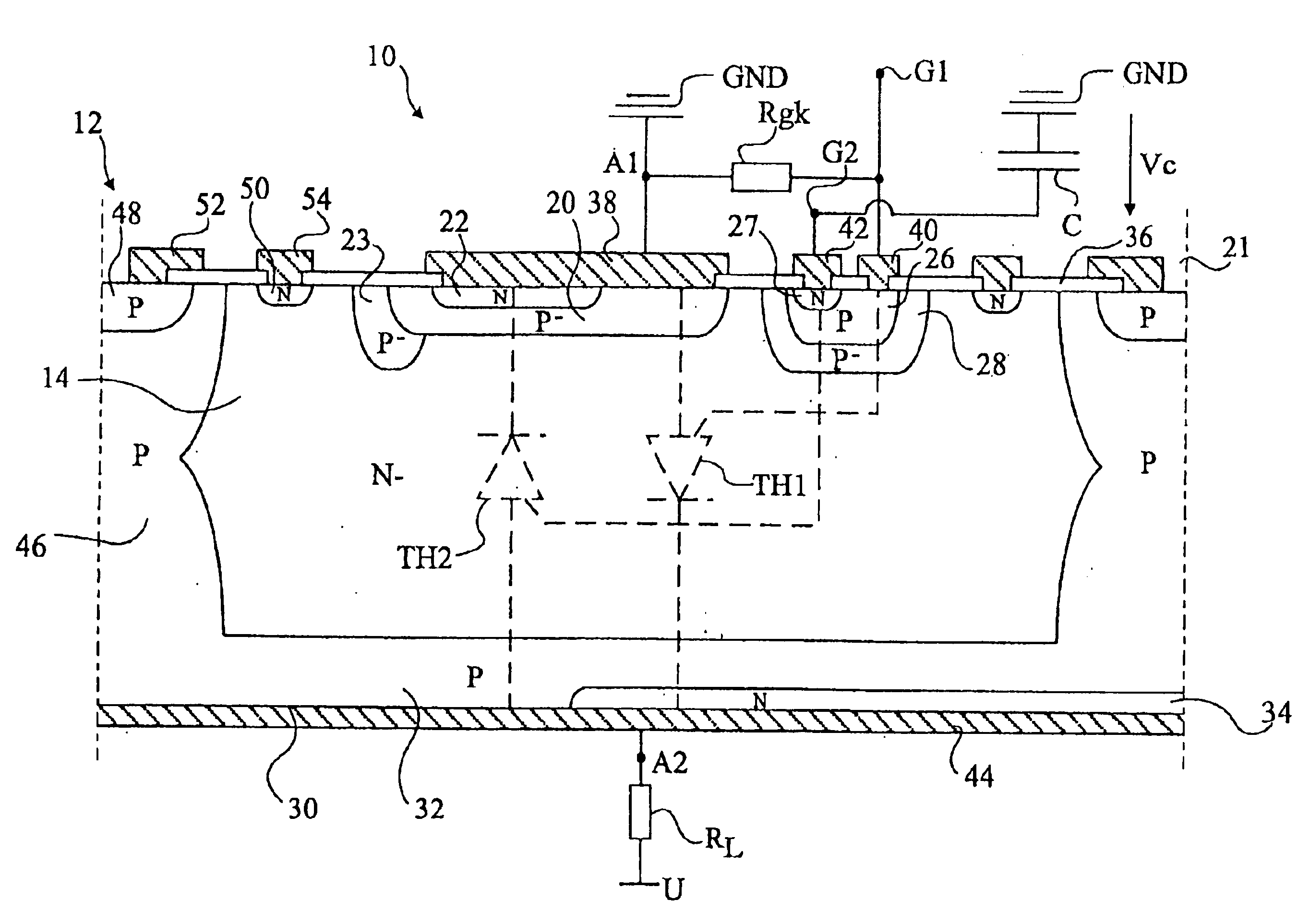
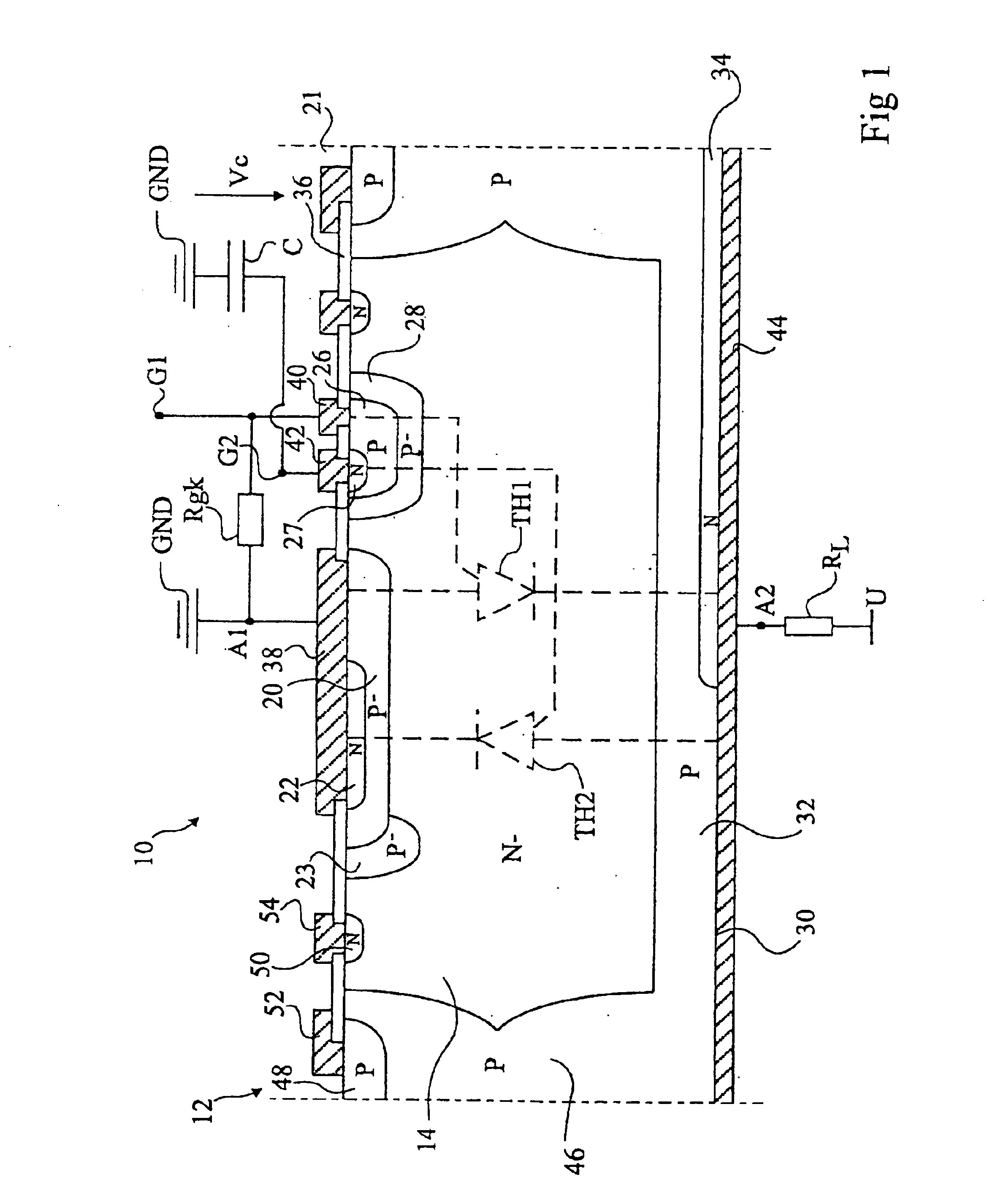
[0031]FIG. 1 shows a bidirectional switch 10 according to the present invention comprising a bidirectional switching device 12 made in monolithic form which is formed of two vertical power thyristors TH1, TH2 arranged in antiparallel between two power terminals A1 and A2. The two thyristors TH1, TH2 are shown in dotted lines.

[0032]Switching device 12 is made in a substrate 14, for example made of lightly-doped N-type silicon. An anode region 20 of first thyristor TH1 is formed on upper surface side 21 of substrate 14. Region 20 contains an N-type cathode region 22 of second thyristor TH2, more heavily doped than substrate 14. A P-type protection region 23 more lightly-doped than region 20 at least partially surrounds region 20. Protection region 23 conventionally enables modifying the distribution of the equipotential surfaces in sub...


PUM


Abstract

A bidirectional switch for switching an A.C. voltage at a load, including a monolithic component, formed in an N-type substrate, including a first vertical thyristor; a second vertical thyristor; a P-type triggering region formed opposite to the cathode of the first thyristor and an N-type triggering region formed in the P-type triggering region, the P-type triggering region being intended to receive a control signal in a negative halfwave of the A.C. voltage to trigger the first thyristor; a resistive element connected to the P-type triggering region and to the anode of the first thyristor; and a capacitor having a terminal connected to the N-type triggering region and its other terminal intended to be connected to the reference voltage.

Description

BACKGROUND OF THE INVENTION[0001]1. Field of the Invention[0002]The present invention relates to the field of high-voltage bidirectional switches. The present invention more specifically relates to a bidirectional switch intended to be series-connected with a load, the assembly being supplied by a high A.C. voltage, for example, the mains.[0003]2. Discussion of the Related Art[0004]High-voltage switches for an A.C. load of the type to which the present invention relates are used, in particular, to control household appliances, for example, washing machines, in which one or several A.C.-supplied loads (motors, pumps, heating resistors, valves) must be controlled from the machine microcontroller.[0005]A bidirectional switch capable of being controlled by a low-voltage signal may be formed of a triac, the gate of which receives a low-voltage control signal.[0006]A triac must be turned on at each halfwave of the supply voltage since it turns off when the current between its two power te...

Claims


Application Information

Patent Timeline
Patent Type & Authority Patents(United States)
IPC IPC(8): H01L29/747H01L29/66
CPCH01L29/747
Inventor MENARD, SAMUEL
Owner STMICROELECTRONICS SRL
Why Eureka
Try Eureka