Circuit and a method for controlling the bias current in a switched capacitor circuit

a switched capacitor and bias current technology, applied in the field of integrated circuits, can solve the problems of significant deviation from the desired design value of the circuit elements, significant influence on the characteristics of passive circuit elements, and inability to accept the respective range of variations in the frequency behaviour of the amplifier, so as to efficiently compensate for environmental fluctuations

Inactive Publication Date: 2005-05-10
ADVANCED MICRO DEVICES INC
View PDF5 Cites 108 Cited by
  • Summary
  • Abstract
  • Description
  • Claims
  • Application Information

AI Technical Summary

Benefits of technology

[0017]Generally, the present invention is based on the inventors finding that measurement and calibration results obtained during tuning a switched capacitor circuit may be used to tune a constant GM bias circuit in order to efficiently compensate for environmental fluctuations, such as temperature variations, and for process induced variations, while at the same time a minimum required bias current is

Problems solved by technology

As is well known in manufacturing circuit elements such as resistors and capacitors unavoidable process variations may lead to significant deviations from a desired design value for the circuit elements.
Moreover, any changes in the environmental conditions, such as temperature variations, may also significantly affect the characteristics of passive circuit elements.
In many applications a respective range of variations in the frequency behaviour of the amplifiers is not acceptable, especially in applications requiring a specified and stable settling time of the amplifiers, as is the case in switched capacitor circuits required for example for filter applications

Method used


Image

  • Circuit and a method for controlling the bias current in a switched capacitor circuit
  • Circuit and a method for controlling the bias current in a switched capacitor circuit
  • Circuit and a method for controlling the bias current in a switched capacitor circuit

Examples


Embodiment Construction

[0028]While the present invention is described with reference to the embodiments as illustrated in the following detailed description as well as in the drawings, it should be understood that the following detailed description as well as the drawings are not intended to limit the present invention to the particular illustrative embodiments disclosed, but rather the described illustrative embodiments merely exemplify the various aspects of the present invention, the scope of which is defined by the appended claims.

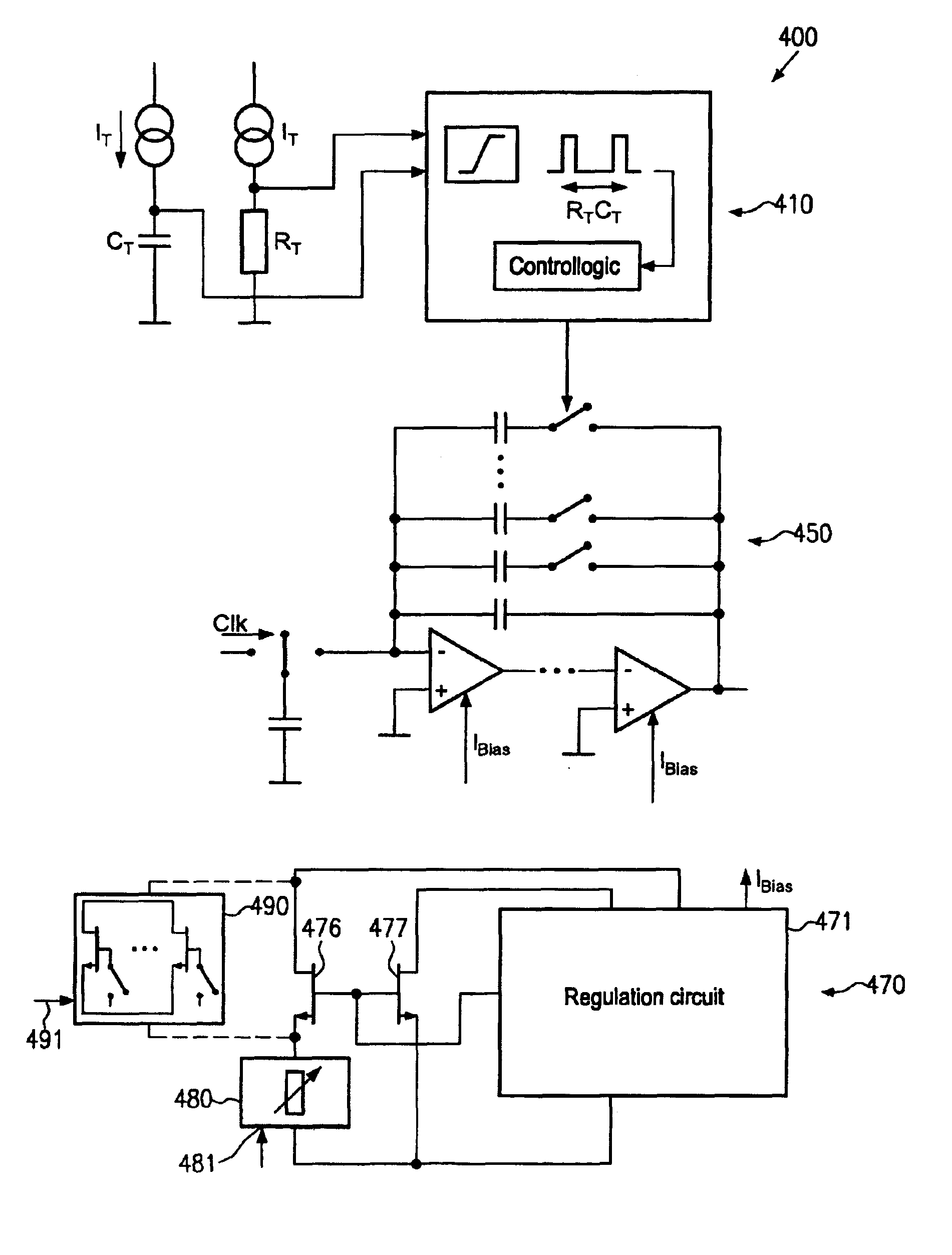
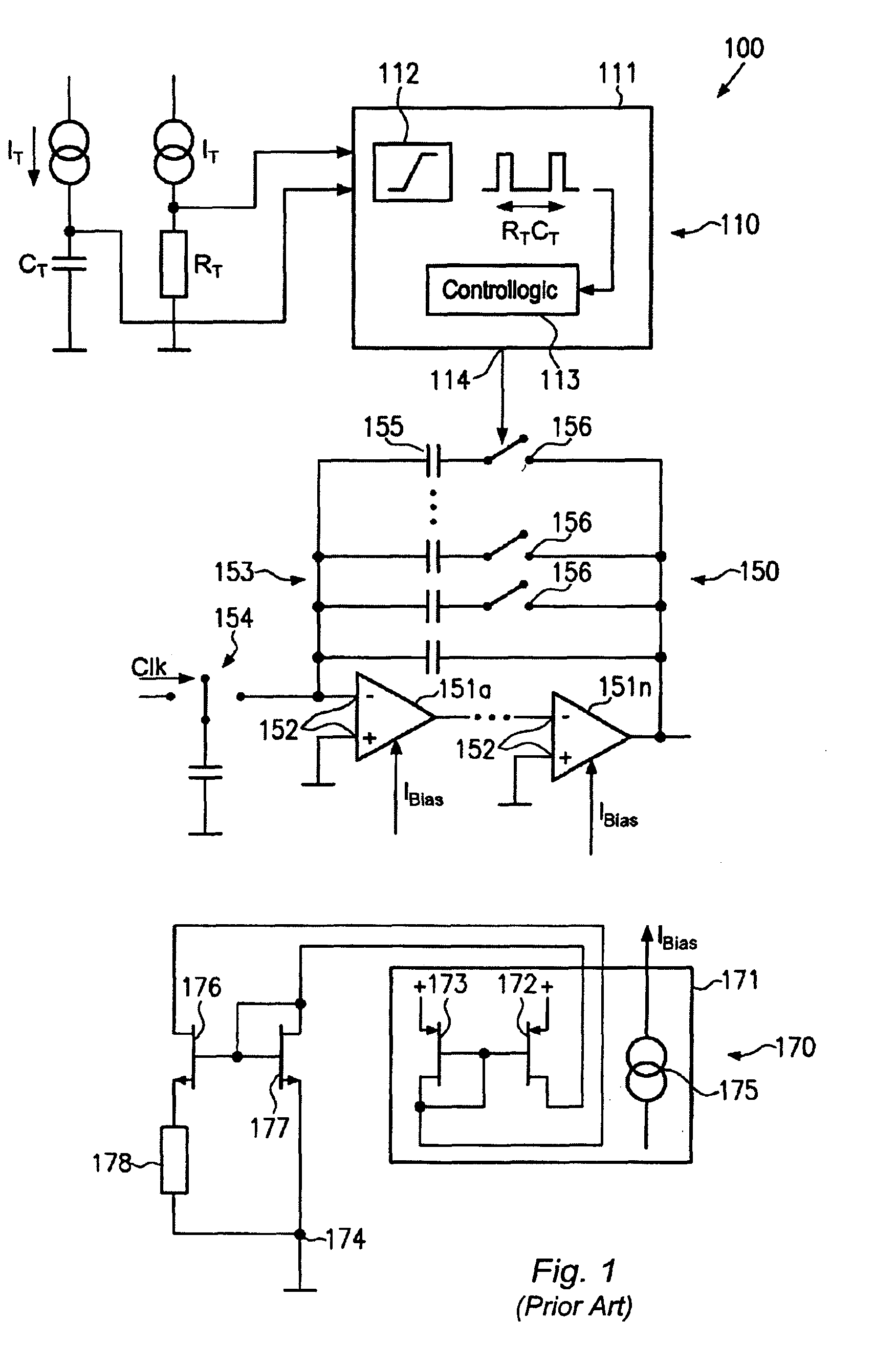
[0029]As previously explained with reference to FIG. 1, the frequency behaviour of a transconductance amplifier biased by a constant GM circuit is substantially determined by:

Ft˜1 / (R×C)×A

wherein A represents the width ratio and R and C may represent the specific values for the resistive material of which the resistor in the constant GM circuit is comprised of and C represents the specific capacitance defined by the design and the technology used for manufacturing the capacit...


PUM


Abstract

A tunable constant GM circuit allows to compensate for temperature and process variations with high precision by correspondingly adjusting a resistance value and/or the ratio of transistor widths. Thus, in switched capacitor circuits the frequency behaviour, such as the settling time, may be controlled by providing a compensated bias to the transconductance amplifiers typically used in these circuits.

Description

FIELD OF THE PRESENT INVENTION[0001]Generally, the present invention relates to integrated circuits including active components, such as transconductance amplifiers, and switched capacitors that may selectively be connected to the transconductance amplifiers to compensate for temperature and process variations.DESCRIPTION OF THE PRIOR ART[0002]In many electronic applications involving the processing of analog signals it is commonly desirable to estimate the frequency behaviour of the circuitry or certain portions thereof. One representative example in this respect are active filter circuits including a plurality of resistors and capacitors connected to a plurality of operational amplifiers, which are in many cases configured as operational transconductance amplifiers (OTA). As is well known in manufacturing circuit elements such as resistors and capacitors unavoidable process variations may lead to significant deviations from a desired design value for the circuit elements. Moreover...

Claims


Application Information

Patent Timeline
IPC IPC(8): H03F3/00H03F1/30
CPCH03F3/005H03F1/304
Inventor JAEHNE, ROLFDATHE, LUTZHUSCHKA, ANDREAS
Owner ADVANCED MICRO DEVICES INC
Why Eureka
Try Eureka