System and method for modeling graphics objects

Inactive Publication Date: 2005-05-10
MITSUBISHI ELECTRIC RES LAB INC
View PDF1 Cites 20 Cited by
  • Summary
  • Abstract
  • Description
  • Claims
  • Application Information

AI Technical Summary

Benefits of technology

[0019]The present invention provides a unified method for modeling objects represented by a wide selection of input geometries. The present method, unlike prior art methods, enable the user to modify the model in real-time. The user can select the required level-of-detail, and

Problems solved by technology

Despite technical advances, hardware and software continue to have limits in the number of polygons they can store and process interactively.
Applications that require quality images, such as movies and medicine, may require a large number of polygons, while other applications, for example, those designed for portable devices, are constrained to using a small number of polygons due to processing and memory limitations.
However, many of these methods exhibit discontinuities during interpolation, and perform poorly, if at all, at lower resolutions due to compounded errors caused by repeated transformations.
To then render these triangles in real-time, as required by games and medical applications, is impractical with current hardware and software methods.
Generating the base mesh can be complicated, leading to the use of decimation methods.
Although vertex clustering is fast, no attempt is made to preserve topology.
This can lead to poor quality approximations of the simplified model, especially when the final number of polygons is much smaller compared to the number of polygons in the input mesh.
An additional disadvantage of the vertex clustering

Method used


Image

  • System and method for modeling graphics objects
  • System and method for modeling graphics objects
  • System and method for modeling graphics objects

Examples


Embodiment Construction
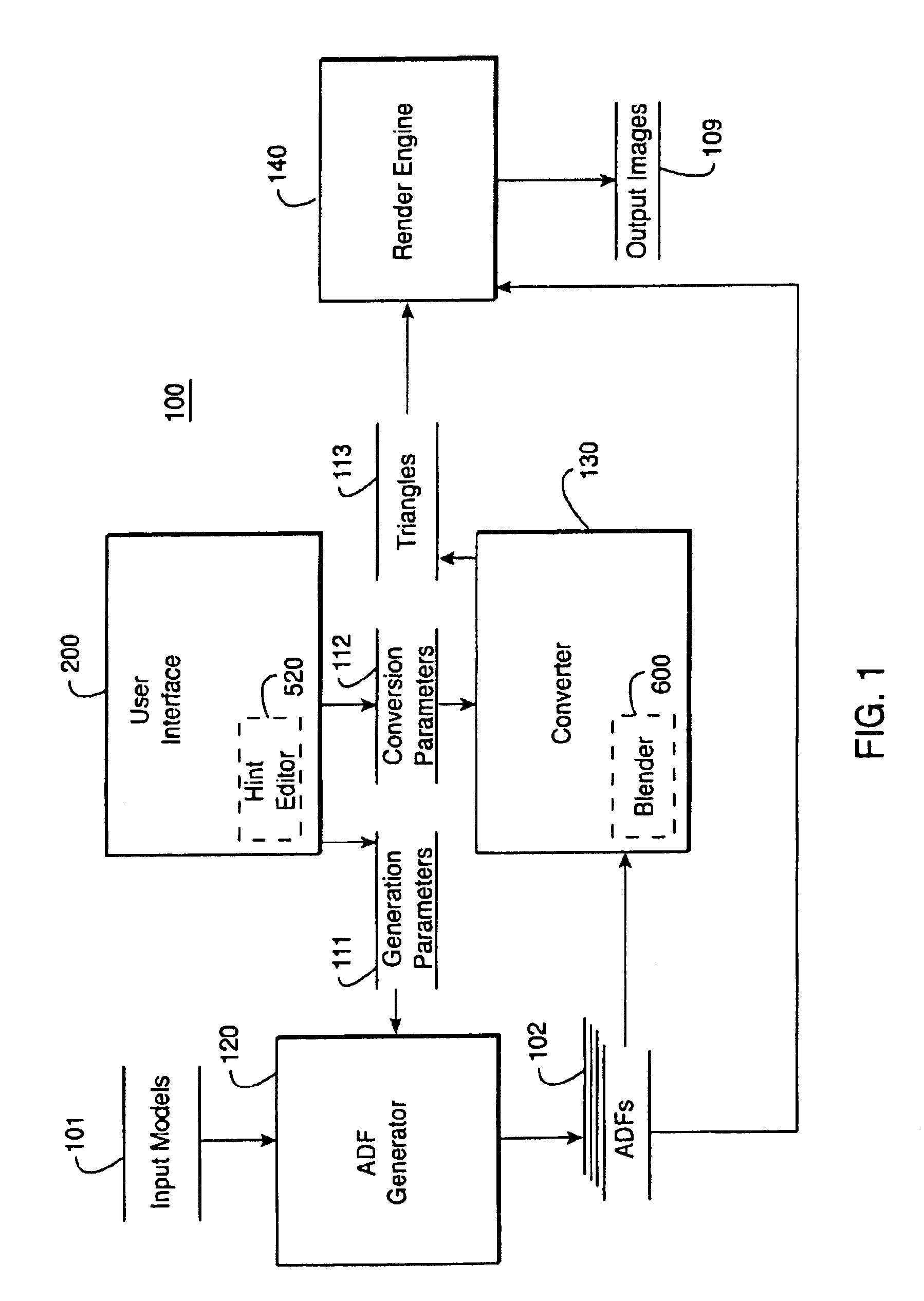
System Overview

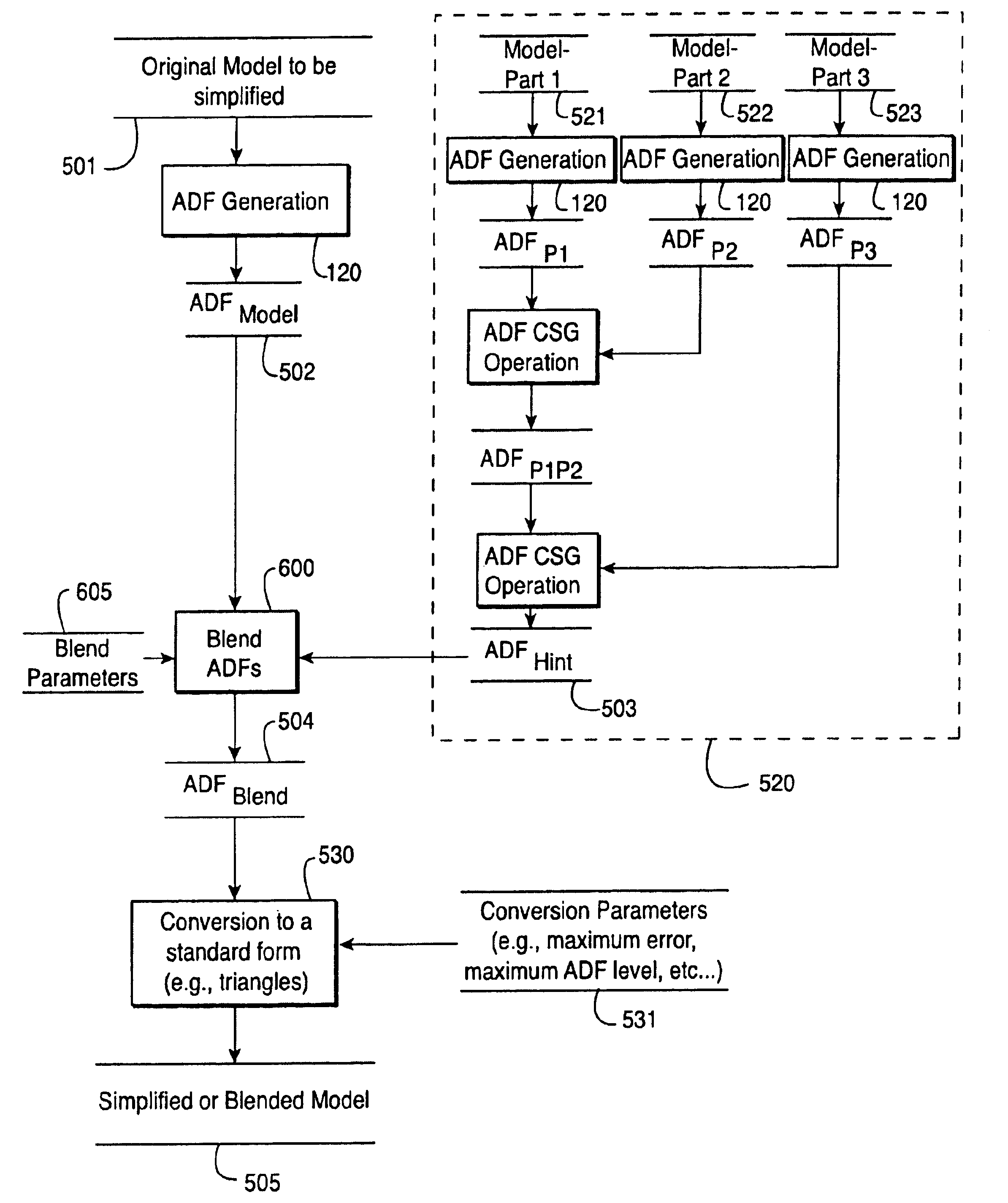
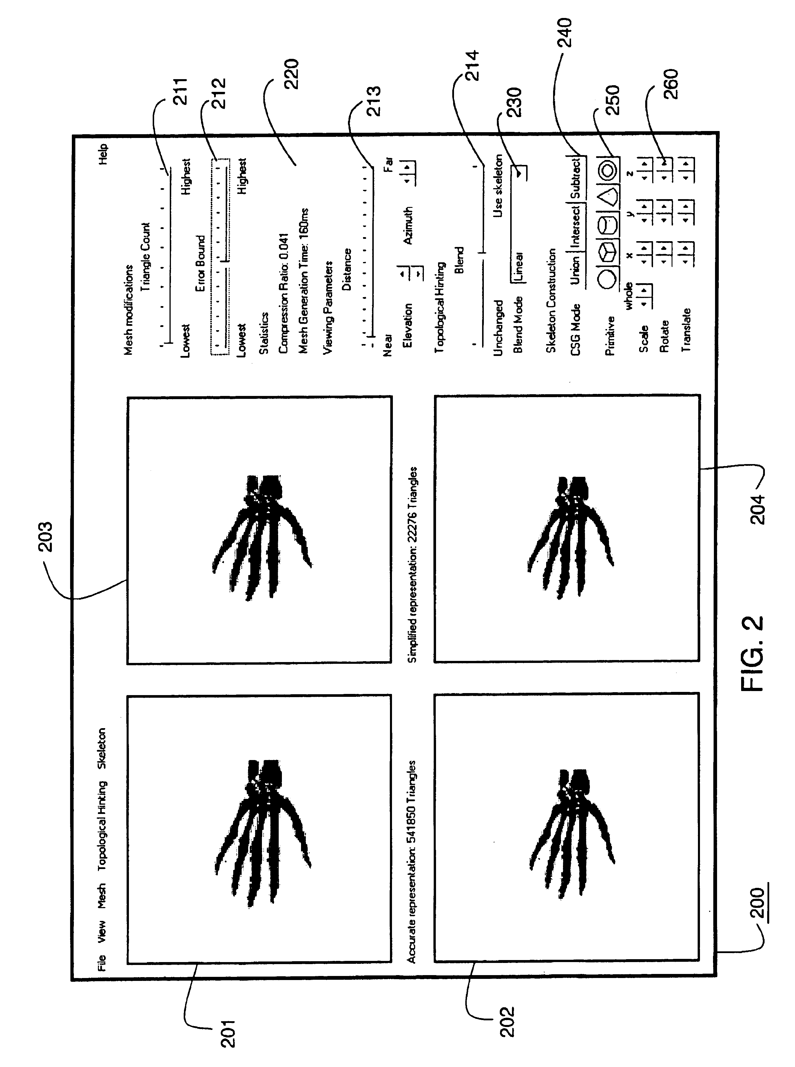
[0030]Our invention provides a method and system for interactively transforming computerized models with simple controls. The user can select important topological features, and provide geometric hints to guide the modeling process at variable levels-of-detail. The invention also allows the user to blend models having different levels of resolution, and perhaps different shapes, while minimizing error, and maximizing quality in the final result.

Adaptively Sampled Distance Fields

[0031]In the preferred embodiment, we represent the input model, having any number of dimensions and a fixed level-of-detail, by an adaptively sampled distance field (ADF). The basic data structure of the ADF is described in U.S. patent application Ser. No. 09 / 370,091 “Detail-Directed Distance Fields” filed by Frisken et al. on Aug. 6, 1999, incorporated herein in its entirety by reference.

[0032]There, the ADF data structure is introduced, basic methods for generating, rendering, and modifying ...


PUM


Abstract

A system models a graphics object by first providing a model of the object, generation parameters specifying a fixed level-of-detail, and conversion parameters specifying variable levels-of-detail. An adaptively sampled distance field having the fixed level-of-detail is generated from the model, and the adaptively sampled distance field is converted from the fixed level-of-detail to the variable levels-of-detail while concurrently generating rendering primitives.

Description

RELATED APPLICATION[0001]U.S. patent application Ser. No. 09 / 810,983 “System and Method for Generating Adaptively Sampled Distance Fields with Bounded Distance Trees” filed by Perry et al. on Mar. 16, 2001; U.S. patent application Ser. No. 09 / 810,839 “Conversion of Adaptively Sampled Distance Fields to Triangles” filed by Frisken et al. on Mar. 16, 2001; U.S. patent application Ser. No. 09 / 810,762 “Modeling Graphics Objects with Topological Hints” filed by Perry et. al. on Mar. 16, 2001; U.S. patent application Ser. No. 09 / 810,977 “Modeling and Combining Multiple Graphics Objects” filed by Perry et al. on Mar. 16, 2001.FIELD OF THE INVENTION[0002]This invention relates generally to the field of computer graphics, and more particularly to constructing models using adaptively sampled distance fields.BACKGROUND OF THE INVENTION[0003]Prior art hardware and software for graphic modeling systems are predominantly designed to store, manipulate, and render models that are represented by pol...

Claims


Application Information

Patent Timeline
IPC IPC(8): G06T17/10
CPCG06T17/10
Inventor PERRY, RONALD N.FRISKEN, SARAH F.POPE, JACKSON W. J.
Owner MITSUBISHI ELECTRIC RES LAB INC
Why Eureka
Try Eureka