

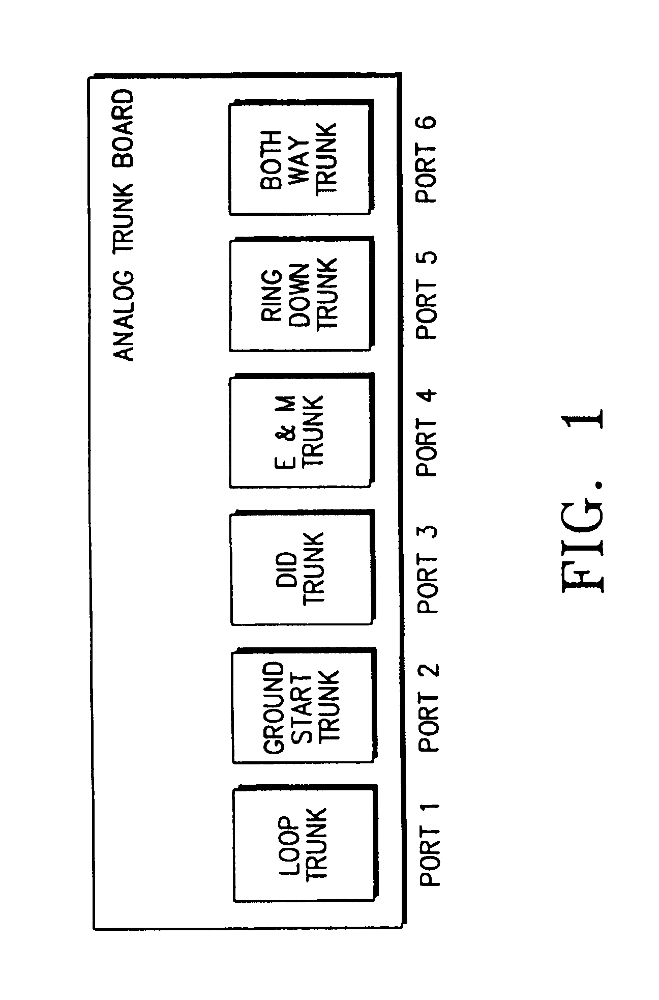
Multifunctional analog trunk circuit
a trunk circuit and multi-functional technology, applied in trunk circuits, main and subordinate switching centres, solid-state devices, etc., can solve the problems of increasing the cost of maintaining the system and many inconveniences, and achieve the effect of increasing productivity and low cos
- Summary
- Abstract
- Description
- Claims
- Application Information
AI Technical Summary
Benefits of technology
Problems solved by technology
Method used
Image

Examples
example 1
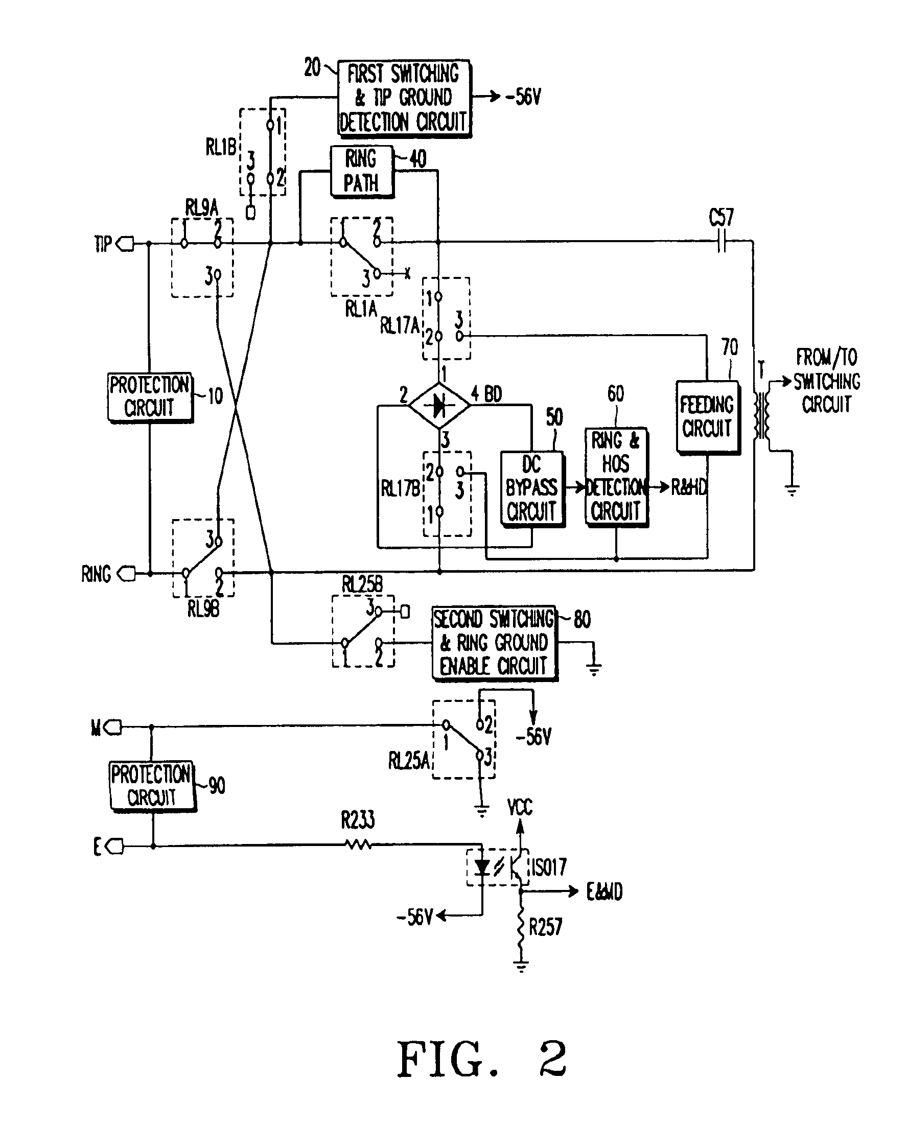
[0034]Referring to FIG. 2, the TRK circuit of the first embodiment comprises protective circuits 10 and 90, first switching & tip ground detection circuit 20, ring path 40, bridge diode BD, DC voltage bypass circuit 50, ring & HOS detection circuit 60, feeding circuit 70, transformer T, second switching & ring ground enable circuit 80, photo coupler ISO17, resistors R233 and R257, and a plurality of relays RL1A, RL1B, RL9A, RL9B, RL17A, RL17B, RL25A, RL25B. Among these, the protective circuit 90, relay RL25A, resistors R233 and R257, and photo coupler ISO17 are the elements to provide for the E&M TRK circuit. The other elements are to provide for the loop, ground start and DID TRK circuits.
[0035]Describing the structure and operation of the multifunctional TRK circuit of the first embodiment with reference to FIGS. 2 and 4, the protective circuits 10 and 90 are respectively connected between the tip terminal TIP and ring terminal RING, and between the “M” terminal and the “E” termin...
example 2
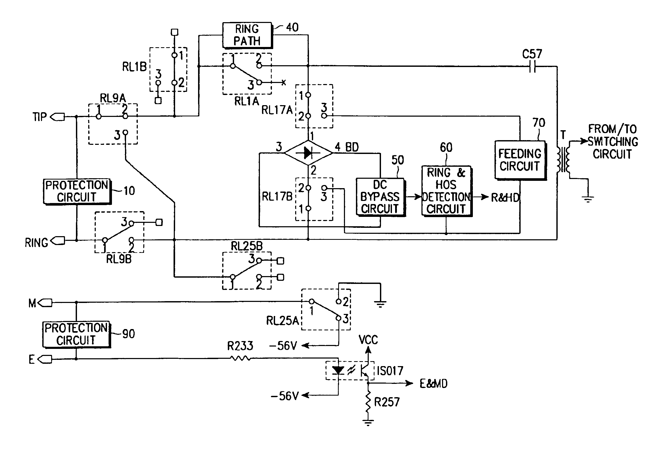
[0065]The circuit according to the second embodiment is, as shown in FIG. 3, designed to serve as both loop, ring down, both way and E&M TRK circuit. This may be effectively applied in a country like Korea. Referring to FIG. 3, the TRK circuit of the second embodiment comprises protective circuits 10 and 90, ring path 40, bridge diode BD, DC voltage bypass circuit 50, ring & HOS detection circuit 60, feeding circuit 70, transformer T, photo coupler ISO17, resistors R233 and R257, and a plurality of relays RL1A, RL1B, RL9A, RL9B, RL17A, RL17B, RL25A, RL25B. Among these, the protective circuit 90, relay RL25A, resistors R233 and R257, and photo coupler ISO17 are the elements to provide for the E&M TRK circuit. The other elements are to provide for the loop, ring down and both way TRK circuits.
[0066]Describing the structure and operation of the multifunctional TRK circuit of the second embodiment with reference to FIGS. 3 and 5, the protective circuits 10 and 90 are respectively connec...
PUM
 Abstract
Description
Claims
Application Information