Method of preparing neural tissue of the brain for subsequent electrical stimulation

a neural tissue and electrical stimulation technology, applied in the field of apparatus and method for electrical stimulation of neural tissue, can solve the problems of unsatisfactory stimulation of dorsal column fibers over dorsal root fibers in a number of directions, restricted paresthesia area, undesirable side effects, etc., and achieves the effect of convenient us

Inactive Publication Date: 2005-05-10
MEDTRONIC INC
View PDF11 Cites 148 Cited by
  • Summary
  • Abstract
  • Description
  • Claims
  • Application Information

AI Technical Summary

Benefits of technology

[0025]It is another object of the invention to provide a system and method for treating pain by SCS by preferentially stimulating dorsal column fibers over dorsal root fibers that is easy to use.
[0026]It is another object of the invention to provide a system and method for electrically stimulating the spinal cord by preferentially stimulating dorsal column fibers over dorsal root fibers that is easy to use.

Problems solved by technology

One of the current problems with SCS is the preferential stimulation of nerve fibers in the dorsal roots (dorsal root nerve fibers) instead of nerve fibers in the dorsal columns (dorsal column fibers) especially at mid-thoracic and low-thoracic vertebral levels.
Stimulation of fibers in one or more dorsal roots results in a restricted area of paresthesia.
It appears that where the distance between the epidurally located electrodes and the spinal cord is large, such as at the mid-thoracic and low-thoracic levels, the method described in the '703 patent may still not sufficiently favor stimulation of the dorsal column fibers over dorsal root fibers in a number of patients (J. Holsheimer et al., Amer J Neuroradiol 1994, 15:951-959).
As a result, the dorsal column fibers that are desired to be stimulated have a lower probability to be stimulated than the dorsal root fibers, which are not desired to be stimulated and which produce the undesirable side effects noted above.

Method used


Image

  • Method of preparing neural tissue of the brain for subsequent electrical stimulation
  • Method of preparing neural tissue of the brain for subsequent electrical stimulation
  • Method of preparing neural tissue of the brain for subsequent electrical stimulation

Examples


Embodiment Construction

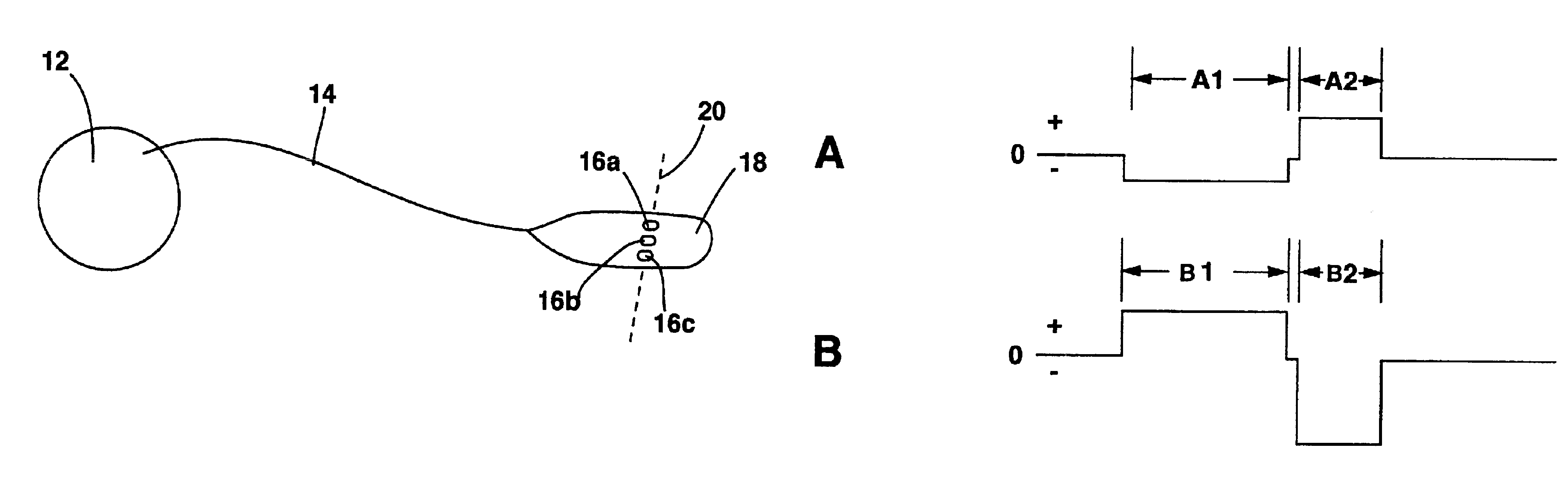
[0034]A system of the present invention is shown in FIG. 5 generally labeled 10. System 10 includes an electric signal generator that is preferably an implantable electric pulse generator (IPG) 12. IPG 12 preferably is a device having at least two channels that may be independently controllable in amplitude, frequency, timing and pulse width. In the preferred embodiment, IPG 12 has two such channels.

[0035]The pulse generator may also be a pulse generator that is connected to an implanted receiver that receives power and programming from an external transmitter by RF coupling. Such a system could be a Matrix® radio-frequency pulse generator available from Medtronic, Inc. of Minneapolis, Minn.

[0036]Alternately, an IPG 12 with three independently controllable channels can be used. In another alternate embodiment, IPG 12 may have a single channel. Such a system could be an Itrel® implantable pulse generator available from Medtronic, Inc. of Minneapolis, Minn. It is also to be understood...


PUM


Abstract

Methods are disclosed of preparing neural tissue of the brain for subsequent electrical stimulation. For example, first, second and third electrodes may be placed in close proximity to tissue of a patient's brain. A hyperpolarizing electrical pre-pulse may be applied to the tissue through the first electrode wherein the tissue is more susceptible to subsequent electric stimulation, or a depolarizing electrical pre-pulse may be applied to the tissue through the first electrode wherein the tissue is less susceptible to subsequent electric stimulation. Other exemplary embodiments are also disclosed.

Description

RELATED APPLICATION[0001]This application is a divisional of prior application Ser. No. 10 / 140,387, filed May 7, 2002, which in turn is a continuation of application Ser. No. 09 / 591,957, filed Jun. 12, 2000, now abandoned, which is a divisional of application Ser. No. 09 / 070,264, filed Apr. 30, 1998, now abandoned.BACKGROUND OF THE INVENTION[0002]1. Field of the Invention[0003]This invention relates to an apparatus and method for electrically stimulating neural tissue including, but not limited to, a spinal cord. More specifically, this invention relates to an apparatus and method for applying a precursor electrical pulse to neural tissue prior to a stimulation pulse with the first pulse “conditioning” the tissue for the application of the stimulation pulse.[0004]2. Description of the Prior Art[0005]Nerve cells in the brain and the spinal cord have a variety of shapes and sizes. A typical nerve cell has the shape shown in FIG. 1 generally labeled 1. The classical parts of nerve cell...

Claims


Application Information

Patent Timeline
Patent Type & Authority Patents(United States)
IPC IPC(8): A61N1/36
CPCA61N1/36035A61N1/3604
Inventor HOLSHEIMER, JAN
Owner MEDTRONIC INC
Why Eureka
Try Eureka