
Tire uniformity machine drive assembly

a technology of drive assembly and uniformity machine, which is applied in vehicle tyre testing, instruments, roads, etc., can solve the problems of introducing additional errors into affecting the fit between the cogs, and affecting the accuracy of the measurement. , to achieve the effect of reducing the influence of the measurement of spindle velocity in the machin

Inactive Publication Date: 2005-05-17
AKRON SPECIAL MACHINERY
View PDF7 Cites 10 Cited by
  • Summary
  • Abstract
  • Description
  • Claims
  • Application Information

AI Technical Summary

Benefits of technology

[0008]In light of the foregoing, at least one object of the present invention is to provide a drive assembly for a tire uniformity machine that has a reduced influence on the measurement of spindle velocity in the machine.

Problems solved by technology

The fit between each cog is limited by machining tolerances introducing some error in the measurement of the spindle's rotation.
Further, the cogs on the timing belt generate significant vibration as they are engaged, introducing additional error into the measurements taken at the tire.
These errors are exacerbated when either the cog wheel or timing belt have bad teeth.
The presence of a bad tooth, i.e., one that is improperly sized or has been damaged or worn causing it to mesh imprecisely with mating teeth, may cause some slipping or other movement of the timing belt relative to the cog wheel or spindle and can often increase the magnitude of the vibration.
The presence of a bad tooth is typically identified by a sudden increase in noise, often a growling sound, or by shaking created by operation of the machine.
As a practical matter, the vibration caused by the presence of teeth, which is increased when bad teeth are present, introduces error in the measurements taken by the tire uniformity machine.
In making the velocity measurement, the teeth on the timing belt cause ripples in the measured velocity, and bad teeth may cause a spike in this measurement.
In effect, errors created by the drive assembly essentially cause a false reading of the spindle's rotational velocity.
Inasmuch as other measurements performed by the tire uniformity machine rely on the accurate measurement of these rotational velocities, the drive assembly errors migrate throughout the tire uniformity machine measurements, in effect, creating a false baseline on which further measurements are superimposed.
As a separate matter, the prior art drive assemblies are bulky and less responsive in making changes in the rotational direction of the tire.
In the majority of prior art system, machine tolerances, and the additional inertia of these components increases the amount of time necessary to reverse the motor and change the direction of the tire or loadwheel.
Reducing the time required to change direction during operation of the tire uniformity machine will result in the processing of a significant number of additional tires in a given period of time.

Method used


Image

  • Tire uniformity machine drive assembly
  • Tire uniformity machine drive assembly
  • Tire uniformity machine drive assembly

Examples


Embodiment Construction

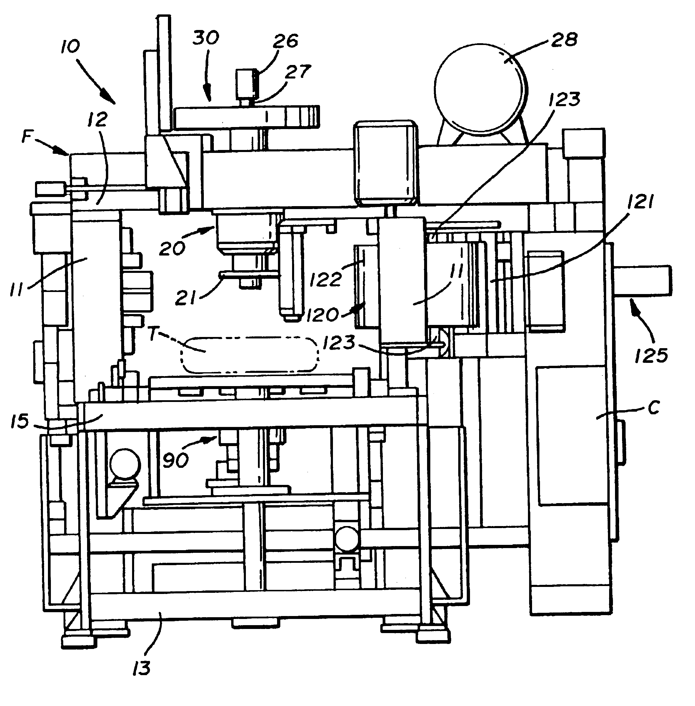
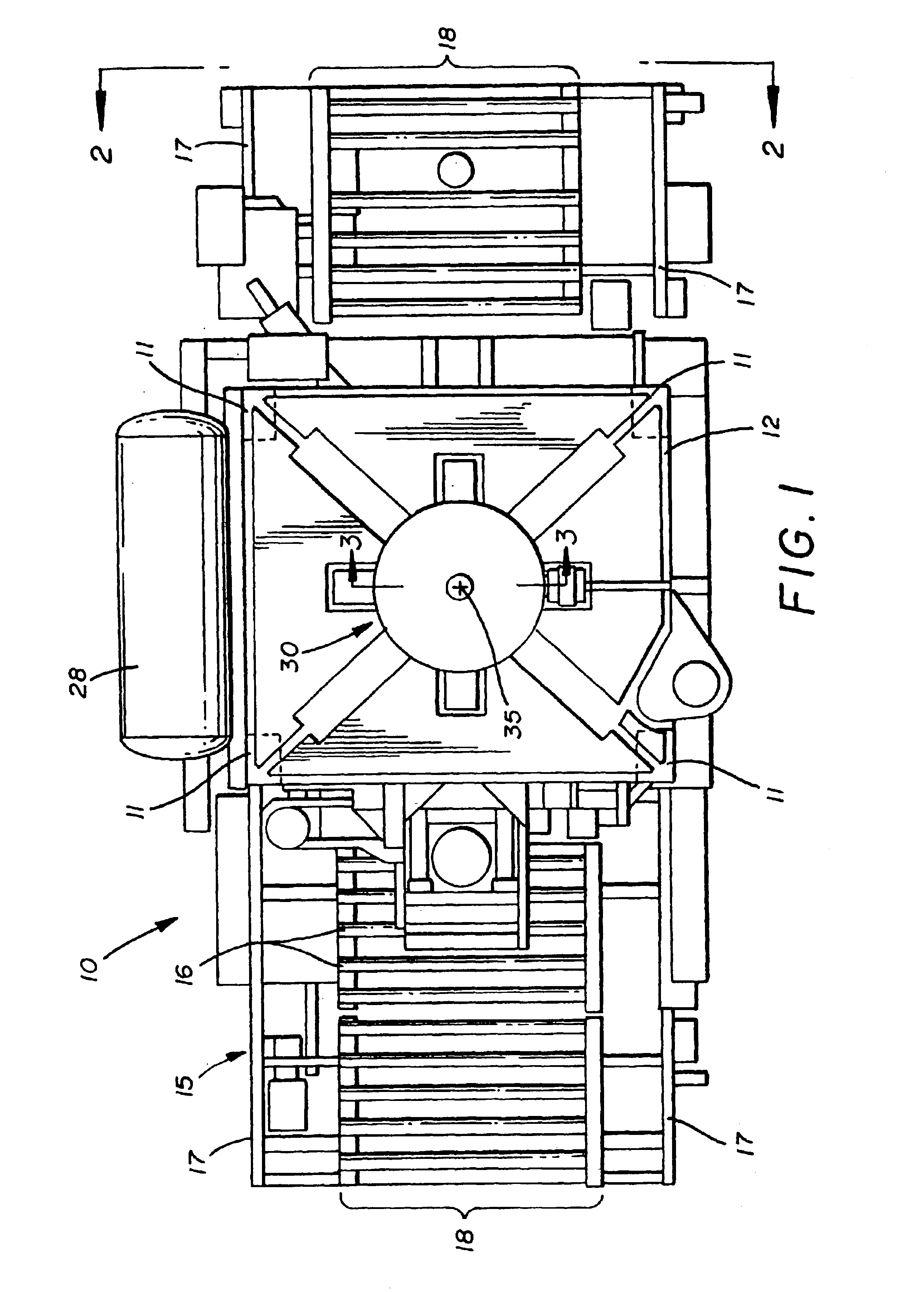
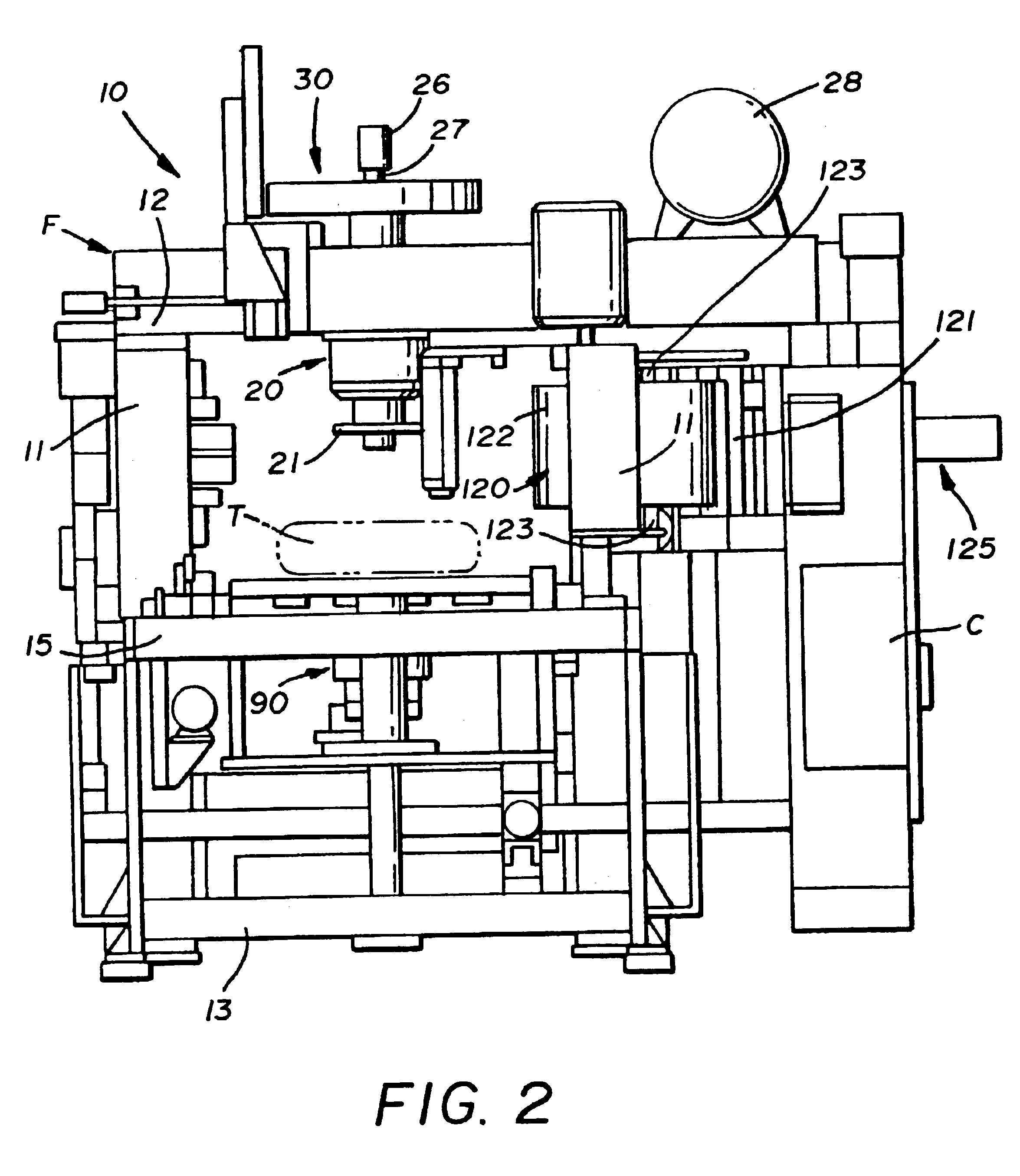
[0017]As can be seen in FIG. 1 of the drawings, a tire uniformity machine, generally indicated by the numeral 10 in the figures, generally includes vertical side frame members 11, a generally horizontal top frame member 12, and generally horizontal bottom frame members 13 to form the framework F for the machine 10. Frame members 11, 12, 13 create a generally box-like structure within which a tire T is received and tested.

[0018]As best shown in FIG. 1, tire T may be delivered into the framework F of the machine 10 and removed therefrom after testing as by a conveyer, generally referred to by the numeral 15. Conveyer 15 may include a plurality of rollers 16 rotatably supported between parallel side members 17 forming a roller bed. The side members 17, 17 of conveyer 15 and side members 11, 11 of machine 10 are generally spaced to an extent such that they are capable of receiving tires of significantly varying diameter. Once the tire T is brought within the framework F of the machine 1...


PUM

PropertyMeasurementUnit
Diameteraaaaaaaaaa
Electric fieldaaaaaaaaaa

Abstract

A tire uniformity machine having a framework for receiving a tire to be tested, a rotatable chuck located within the framework and having a spindle driven by a motor directly coupled to the spindle to selectively cause rotation thereof, whereby the tire is chucked within the chuck assembly and caused to rotate by the motor. The motor is disposed in axial alignment with the spindle.

Description

RELATED PATENT APPLICATIONS[0001]This application is a continuation of U.S. application Ser. No. 09 / 849,824 filed May 7, 2001 now U.S. Pat. No. 6,584,877.FIELD OF THE INVENTION[0002]In general, the present invention relates to tire uniformity machines. More particularly, the present invention relates to a drive assembly in a tire uniformity machine. Most particularly, the present invention relates to a spindle drive assembly in a tire uniformity machine.BACKGROUND OF THE INVENTION[0003]Generally, tire uniformity machines are used to test the characteristics of tires after production. This testing may include measurement of the dimensional characteristics of the tire and the forces on the tire at varying loads. To accomplish load testing, the tire is brought into the tire uniformity machine, mounted on a chuck, inflated and rotated by a drive assembly coupled to the spindle of the chuck while a load wheel is brought into contact with the periphery of the tire.[0004]Previously, these ...

Claims


Application Information

Patent Timeline
IPC IPC(8): G01M17/02G01M1/16B60C19/00
CPCG01M17/022Y10T82/16967Y10T82/26Y10T82/25G01M17/02
Inventor POLING, SR., DAVIDDELMORO, RICHARD L.KRAUSE, DAVID P.
Owner AKRON SPECIAL MACHINERY
Learn More