Fuel/air separation system

a separation system and air technology, applied in separation processes, filtration separation, liquid degasification, etc., can solve the problems of air pressure, power loss, air pressure loss,

Active Publication Date: 2005-05-17
EKSTAM CHARLES BRADLEY
View PDF47 Cites 30 Cited by
  • Summary
  • Abstract
  • Description
  • Claims
  • Application Information

AI Technical Summary

Problems solved by technology

If air or other gaseous vapor is entrained with the fuel and injected into the cylinder, the air/fuel ratio may be affected resulting in a rough running engine and loss of power and efficiency.
Additio...

Method used


Image

  • Fuel/air separation system
  • Fuel/air separation system
  • Fuel/air separation system

Examples


Embodiment Construction

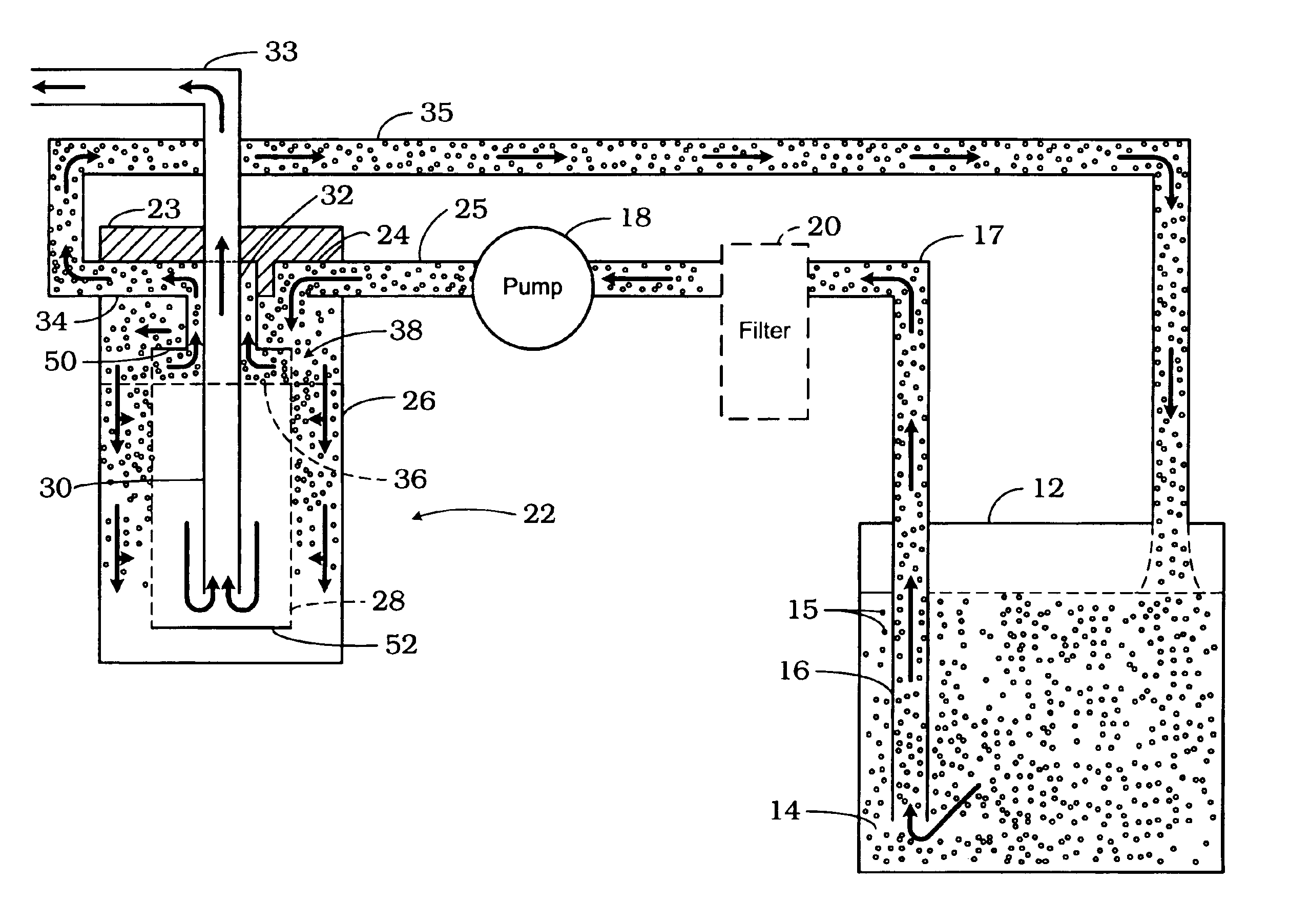
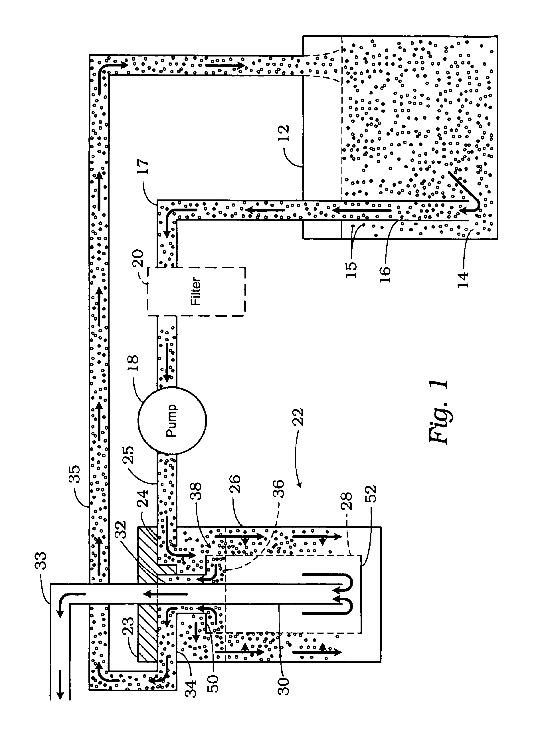
[0007]Referring to FIG. 1, an illustration of a fuel system for use in a vehicle (not shown) is generally indicated by reference numeral 10. The fuel system 10 includes a fuel tank 12 for storing fuel 14, and a fuel intake 16 to draw fuel 14 from tank 12 under a vacuum from pump 18. The input of pump 18 is connected to an optional fuel filter or water separator 20 to separate out particle contaminants such as dirt and rust particles and / or water from the fuel 14. The output of pump 18 is connected to fuel / air separation apparatus 22.

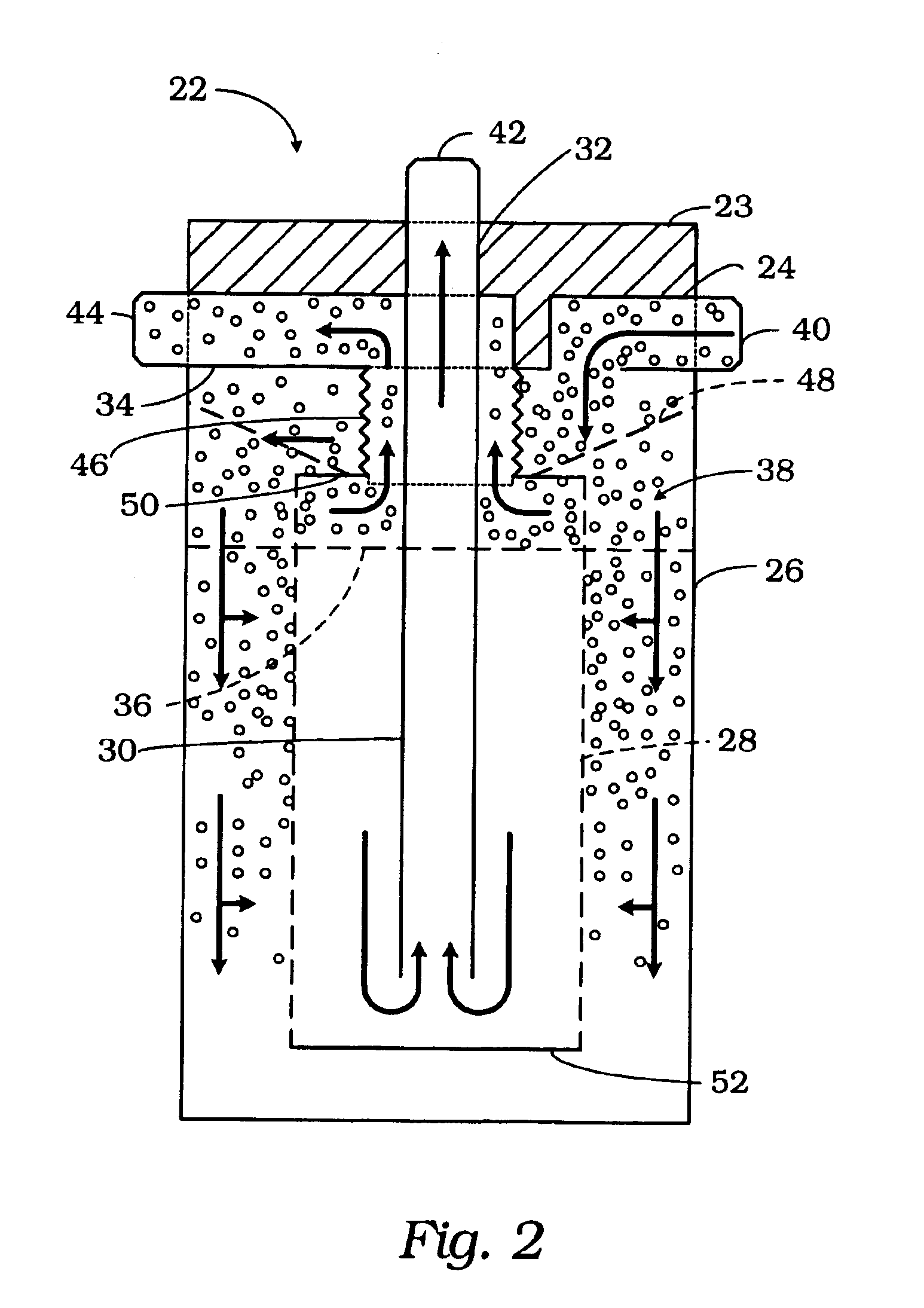
[0008]Fuel / air separation apparatus 22 includes an inlet port 24, a hallow canister 26, a filter element 28, a draw tube 30, a fuel port 32 and an air / vapor / fuel return port 34.

[0009]Fuel 14 in tank 12 includes air and vapor bubbles 15 mixed with the fuel 14. As the fuel 14 is drawn into the fuel intake tube 16, the entrained air / vapor bubbles 15 are carried along with the fuel 14 into the fuel line 17. Fuel 14 in line 17 may also include other debris su...


PUM


Abstract

A fuel/air separation apparatus for separating air and/or vapor from a liquid fuel. The apparatus includes a canister and filter element which separates the entrained air and/or vapor from the fuel and provides substantially air/vapor-free fuel for use by an engine and returns the filtered air/vapor and any excess fuel to the vehicle's fuel tank.

Description

CROSS-REFERENCE TO RELATED APPLICATION[0001]This application claims the benefit of a prior filed, co-pending application Ser. No. 60 / 449,518, filed Feb. 21, 2003, entitled FUEL / AIR SEPARATION SYSTEM.BACKGROUND OF THE INVENTION[0002]This invention relates to an apparatus for removing entrained gas from a liquid and, more particularly, to a fuel / air separation apparatus to remove entrained particle contaminants, air and vapor from a liquid.[0003]Today's internal combustion engines typically utilize a fuel injection type system to inject fuel into the engine cylinder. The fuel is delivered to the cylinder in precise quantity of air. The ratio of air / fuel mixture is tightly controlled in order to maintain a smooth and efficient running engine. If air or other gaseous vapor is entrained with the fuel and injected into the cylinder, the air / fuel ratio may be affected resulting in a rough running engine and loss of power and efficiency. Air and / or vapor in a fuel injector delays injection ...

Claims


Application Information

Patent Timeline
IPC IPC(8): B01D36/00F02M37/20F02M37/22B01D17/00B01D19/00
CPCB01D17/00B01D19/0031B01D36/001F02M37/20F02M37/22B01D17/04B01D17/10F02M37/221F02M37/24F02M37/34F02M37/54
Inventor EKSTAM, CHARLES BRADLEY
Owner EKSTAM CHARLES BRADLEY
Why Eureka
Try Eureka