Flow control valve with integral sensor and controller and related method

Active Publication Date: 2005-05-17
HONEYWELL INT INC
View PDF41 Cites 66 Cited by
  • Summary
  • Abstract
  • Description
  • Claims
  • Application Information

AI Technical Summary

Benefits of technology

[0006]The present invention provides an apparatus and method for measuring and controlling fluid flow through a variable are

Problems solved by technology

The control valves presently known may be either mechanically complex or simple.
One mechanically complex control valve may have a relatively heavy, complex, and expensive all mechanical servo valve that both measures and controls fluid flow rate.
For example, the mechanically complex valve may have limi

Method used


Image

  • Flow control valve with integral sensor and controller and related method
  • Flow control valve with integral sensor and controller and related method
  • Flow control valve with integral sensor and controller and related method

Examples


Embodiment Construction

[0014]Before proceeding with the detailed description, it is to be appreciated that the present invention is not limited to the embodiment described herein. Thus, although the present embodiment is, for convenience of explanation, depicted and described as a flow control valve with a system that is used to determine and control mass flow rate, it will be appreciated that it can be used to determine and control other fluid flow properties, such as volumetric flow rate and heat flow rate.

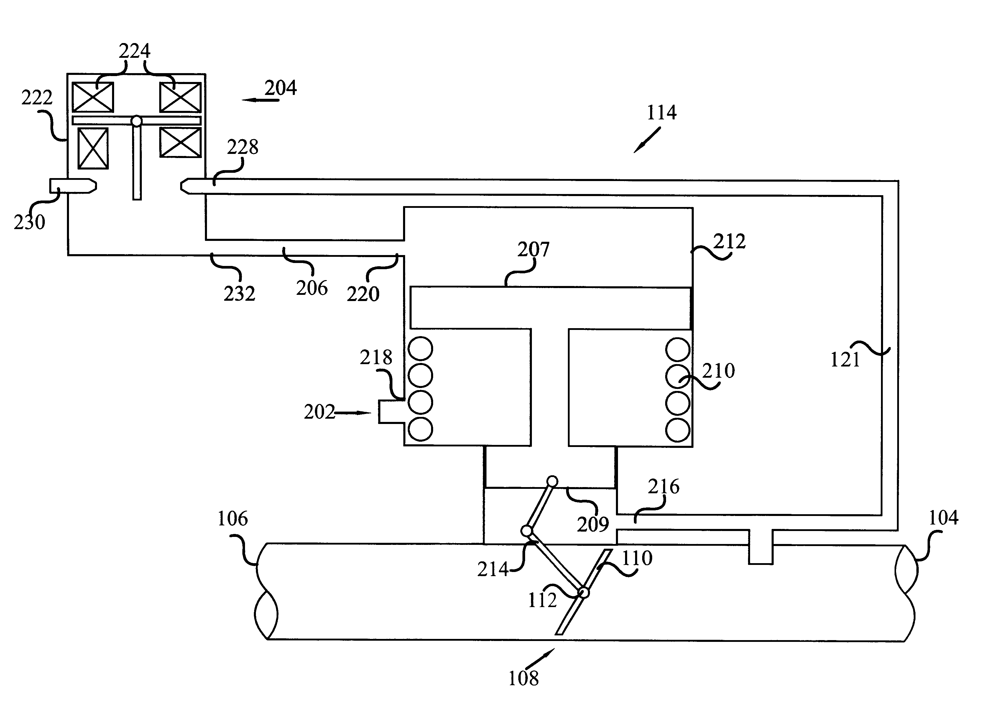
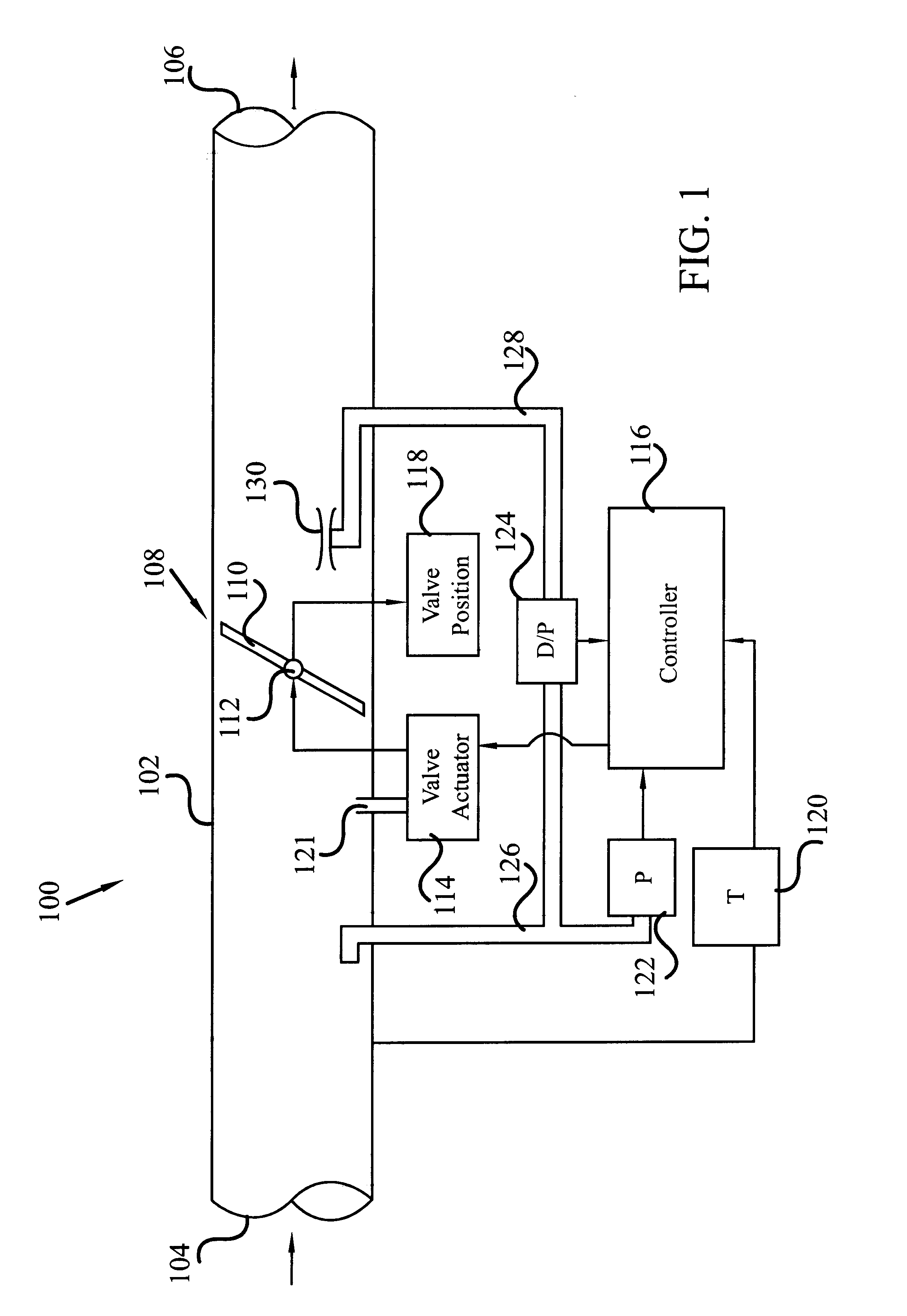
[0015]Turning now to the detailed description, a schematic representation of a flow control valve is depicted in FIG. 1. The flow control valve 100 includes a passageway 102 that has an inlet opening 104 and an outlet opening 106. The fluid whose flow rate is being controlled flows into the inlet 104 and exits the outlet 106. The valve can be used to measure and control the flow rate of various types of fluid, including both liquids and gasses. In a preferred embodiment, however, the fluid is a gas, s...


PUM


Abstract

A flow control valve assembly, and a method of determining and controlling fluid flow through the valve, that is relatively simple in design, is relatively inexpensive, is accurate, and has a relatively wide measurement range. The flow control valve is relatively compact and includes all of the flow measurement and control components in a single, relatively compact assembly. Such components may include a differential pressure sensor, pressure sensor, a temperature sensor, a position sensor, and a processor. The differential pressure sensor senses differential pressure across the variable area flow orifice. The pressure sensor senses fluid pressure within the valve and supplies a fluid pressure signal. The temperature sensor senses fluid temperature and supplies a fluid temperature signal. The position sensor senses the position of the variable area flow orifice and supplies a position signal. The processor receives the differential pressure signal, the fluid pressure signal, the fluid temperature signal, and the position signal and uses these signals to determine and control fluid flow parameter in the passageway.

Description

BACKGROUND OF THE INVENTION[0001]The present invention relates to an apparatus and method for measuring and controlling fluid flow in a valve or passageway and, more particularly, to an apparatus and method for measuring and controlling fluid flow through a variable area flow orifice within the valve or duct.[0002]Systems and methods for measuring and controlling fluid flow in a system are found in various industries. For example, various air distribution systems in commercial aircraft use various devices for measuring and controlling the flow of air through numerous branch lines that feed different portions of the aircraft. The flow of air through these branch lines may be controlled by a control valve, in response to a flow rate measurement.[0003]The control valves presently known may be either mechanically complex or simple. One mechanically complex control valve may have a relatively heavy, complex, and expensive all mechanical servo valve that both measures and controls fluid f...

Claims


Application Information

Patent Timeline
IPC IPC(8): G01F1/34G01F1/36G05D7/06
CPCG05D7/005G01F1/363Y10T137/0318Y10T137/7762Y10T137/7764
Inventor BENSON, DWAYNE M.
Owner HONEYWELL INT INC
Why Eureka
Try Eureka