
Method and apparatus for application of pressure to a workpiece by thermal expansion

a technology of thermal expansion and workpiece, applied in the direction of soldering apparatus, press ram,auxillary welding device, etc., can solve the problems of large capital expenditures to maintain sufficient tools to meet capacity needs, large capital expenditures to maintain the size of the typical apparatus, and high operating costs associated with the operation and maintenance of the typical apparatus. , to achieve the effect of less space requirements

Inactive Publication Date: 2005-05-17
IBM CORP
View PDF12 Cites 34 Cited by
  • Summary
  • Abstract
  • Description
  • Claims
  • Application Information

AI Technical Summary

Benefits of technology

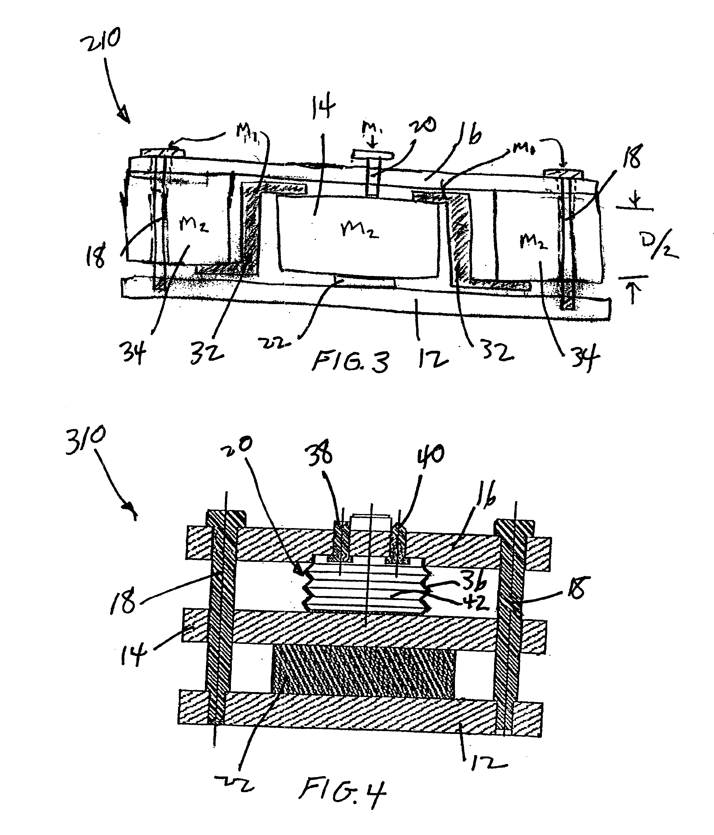
[0030]FIG. 3 is a partial cross-sectional view of the fixture of FIG. 1 modified to apply pressure to a workpiece with less space requirements.

Problems solved by technology

Another deficiency is that the typical apparatus requires large capital expenditures.
A further deficiency is large capital expenditures to maintain sufficient tools to meet capacity needs.
A last deficiency is the high operating costs associated with the operating and maintenance of the typical apparatus.

Method used


Image

  • Method and apparatus for application of pressure to a workpiece by thermal expansion
  • Method and apparatus for application of pressure to a workpiece by thermal expansion
  • Method and apparatus for application of pressure to a workpiece by thermal expansion

Examples


Embodiment Construction

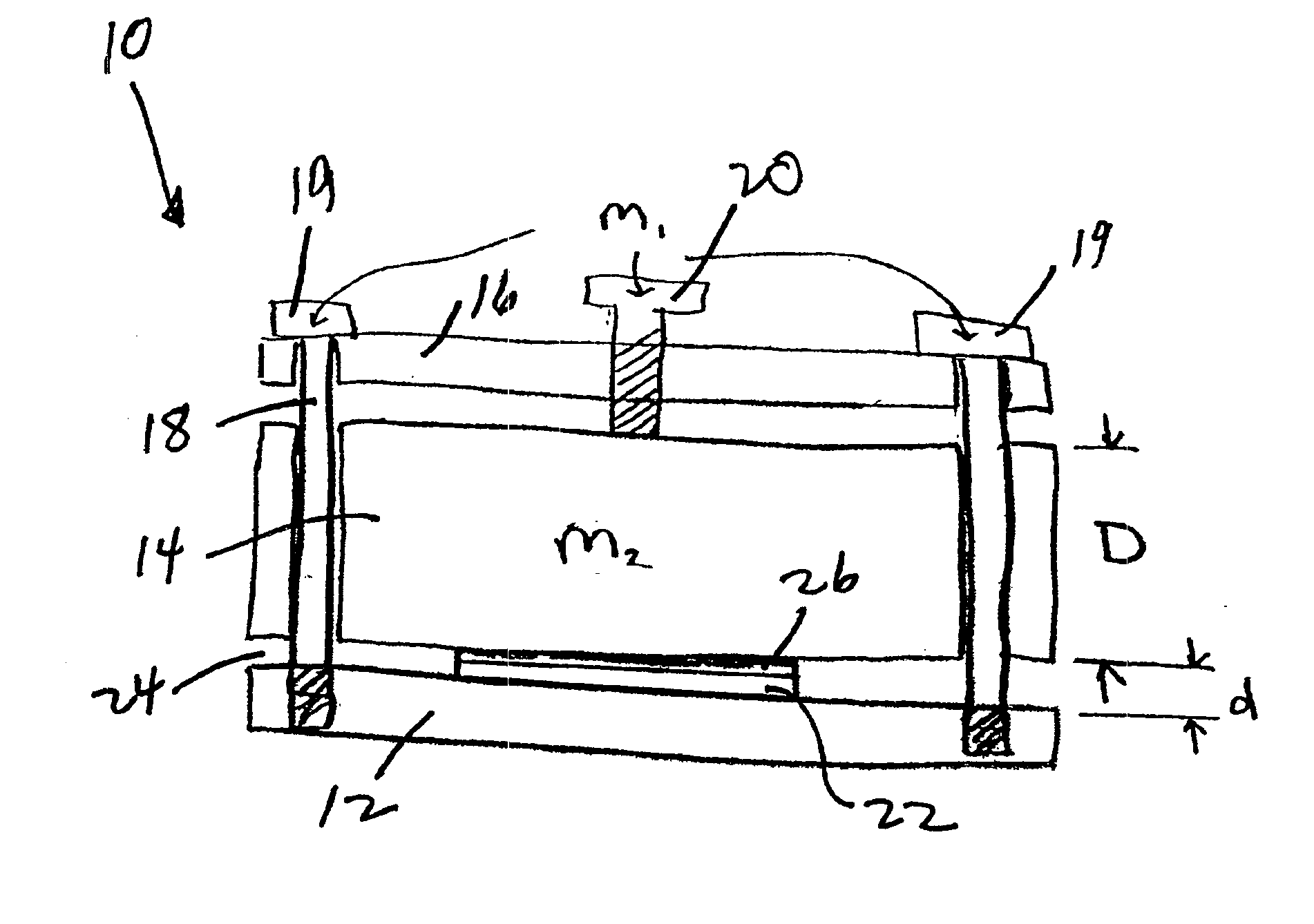
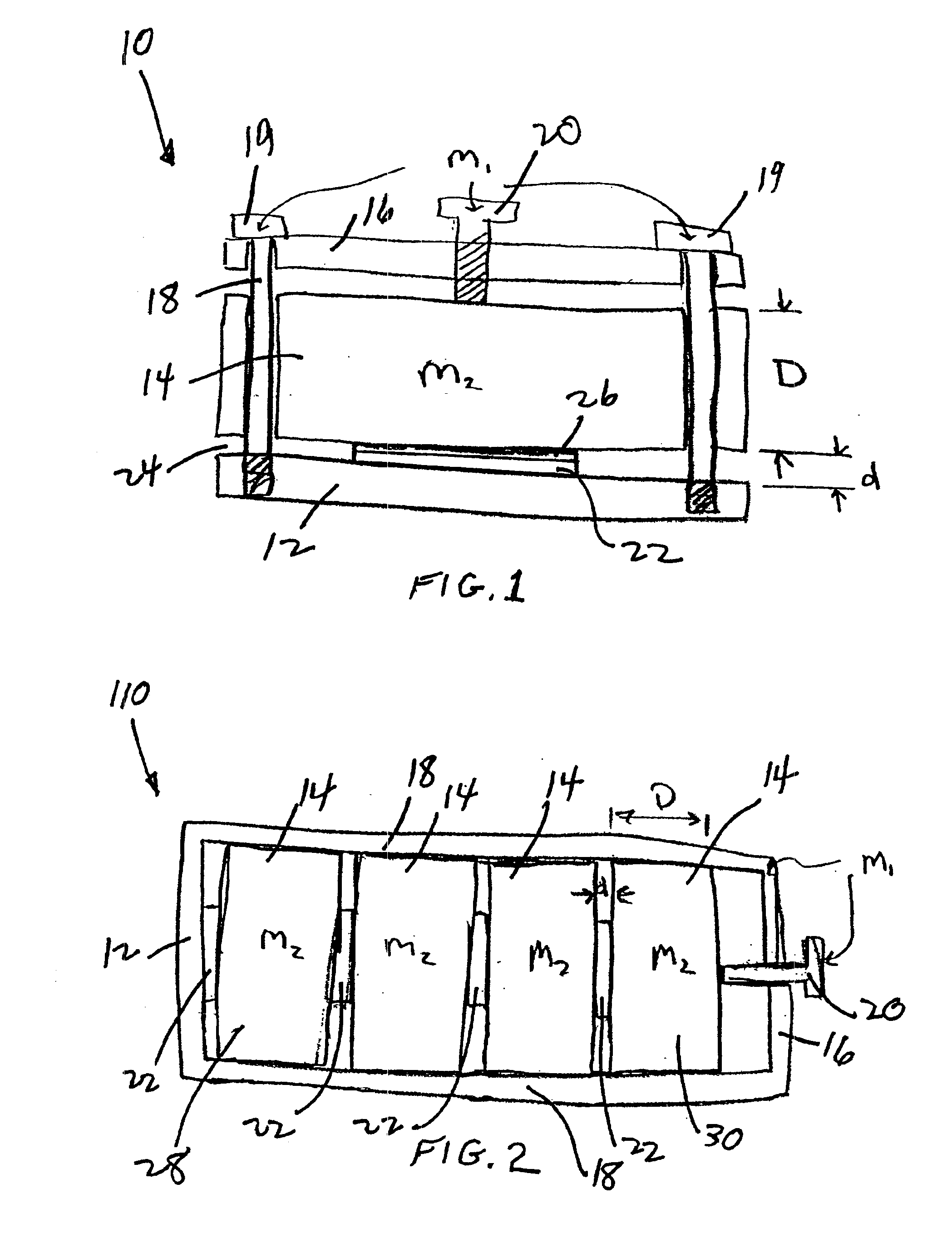
[0033]Referring to the Figures in more detail, and particularly referring to FIG. 1, there is shown a fixture 10 according to the present invention for applying heat and pressure to a workpiece 22. The fixture 10 includes a bottom plate 12 which forms the base of the fixture 10, a top plate 16 forming the top of the fixture 10, and an expansion block 14 interposed between the bottom plate 12 and top plate 16. The fixture 10 further comprises alignment means 18 for aligning the top plate 16 and bottom plate 12 with respect to each other. Preferably, the expansion block 14 is also aligned with the top plate 16 and bottom plate 12 by alignment means 18. In one preferred embodiment, alignment means 18 comprises at least two bolts, screws or similar fastening devices as shown in FIG. 1. The fastening device 18 is threaded into bottom plate 12 but is not threaded into expansion block 14 and top plate 16. In this manner, expansion block 14 and top plate 16 are captured between the head 19 ...


PUM

PropertyMeasurementUnit
thickaaaaaaaaaa
thickaaaaaaaaaa
thickaaaaaaaaaa

Abstract

A fixture having a bottom plate, top plate and an expansion block interposed between the bottom plate and top plate. A workpiece is positioned between the expansion block and bottom plate. When the fixture is heated, there is a net displacement exerted by the expansion block so as to apply pressure to the workpiece. The pressure applied by the fixture to the workpiece is due solely to the thermal expansion of the fixture when it is heated.

Description

BACKGROUND OF THE INVENTION[0001]The present invention relates generally to the application of pressure to a workpiece and, more particularly, relates to the application of pressure to a workpiece solely by thermal expansion of the fixture holding the workpiece.[0002]Increasing demands are emerging for higher performance semiconductor packages. To meet these demands, interconnection designs have been proposed using thin film technology, including multilayer thin film (MLTF) structures.[0003]MLTF structures are composed of metal and dielectric layers comprising, among other materials, copper and polyimide. Such structures are used in the microelectronics industry to interconnect semiconductor devices (also referred to as chips). The interconnect structure includes alternating layers of electrically insulating and conducting materials. Vias in the insulating material provide electrical connections between the conductor layers and bond pad terminations on semiconductor devices. The num...

Claims


Application Information

Patent Timeline
Patent Type & Authority Patents(United States)
IPC IPC(8): B30B1/00H01L21/00
CPCB30B1/005B32B37/10H01L21/67103H01L21/67092Y10T156/16
Inventor MCHERRON, DALE CPATEL, KAUSHAL S.TESSLER, CHRISTOPHER LEEGORRELL, JERRY A.TERSIGNI, JAMES EDWARD
Owner IBM CORP
Learn More