
Frequency correction for drop size control

a drop size and frequency correction technology, applied in printing and other directions, can solve the problems of increasing the sensitivity of the fluid level in the reservoir, affecting the accuracy of drop size correction, and general undesirable drop size variations

Inactive Publication Date: 2005-05-17
LABCYTE
View PDF18 Cites 6 Cited by
  • Summary
  • Abstract
  • Description
  • Claims
  • Application Information

AI Technical Summary

Benefits of technology

The present invention provides devices and methods for ejecting fluid droplets onto a substrate surface using acoustic energy. The device includes a reservoir for containing fluid, an ejector for generating acoustic radiation, and a focusing means to emit a droplet from the surface of the fluid. The device can measure the distance between the surface of the fluid and the focusing means to select the frequency and amplitude of the RF signal for ejecting a droplet of desired size and velocity. The method can be repeated with multiple reservoirs containing different fluids to generate an array of molecular moieties on the substrate surface. The technical effects include improved accuracy and control over droplet size and velocity, as well as the ability to generate arrays of molecules on a substrate surface.

Problems solved by technology

Such a variation in drop size is generally undesirable.
While above-discussed patents described some of the principles behind the invention described herein, they fail to provide a specific description of a system and method for drop size correction suitable for use in an acoustic drop ejection system utilizing multiple wells wherein there is variation in the height of the ejected fluids in different wells.
Unfortunately, low F-number lenses place restrictions on the reservoir and fluid level geometry and provide relatively limited depth of focus, increasing the sensitivity to the fluid level in the reservoir.
Furthermore, the prior art fails to describe any systems or methods that maintain a constant drop size when there are variations in fluid heights without the need for maintaining focus relative to the fluid surface or changing to relative position of the lens with respect to the fluid surface as the lens moves from reservoir to reservoir.

Method used


Image

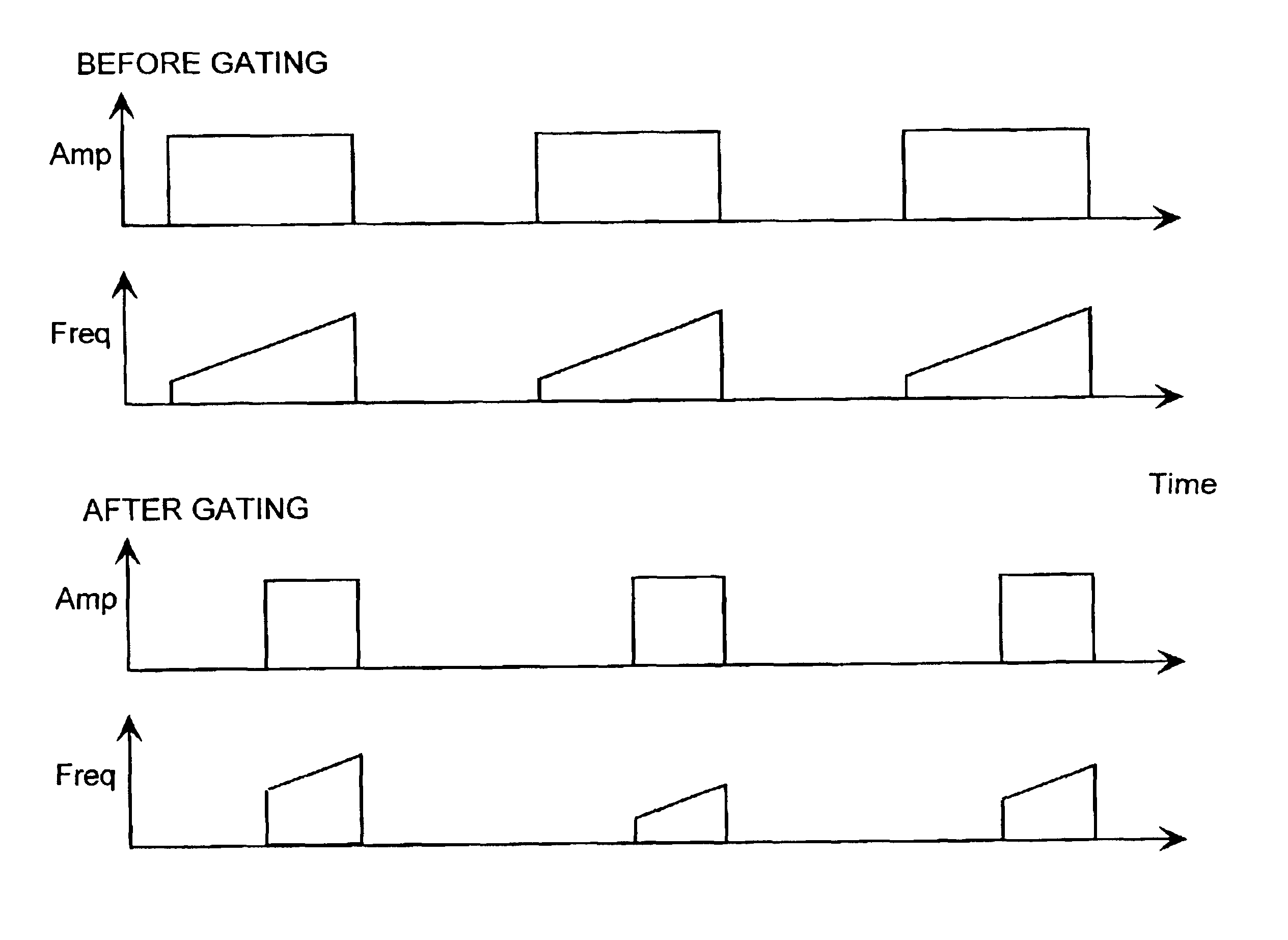
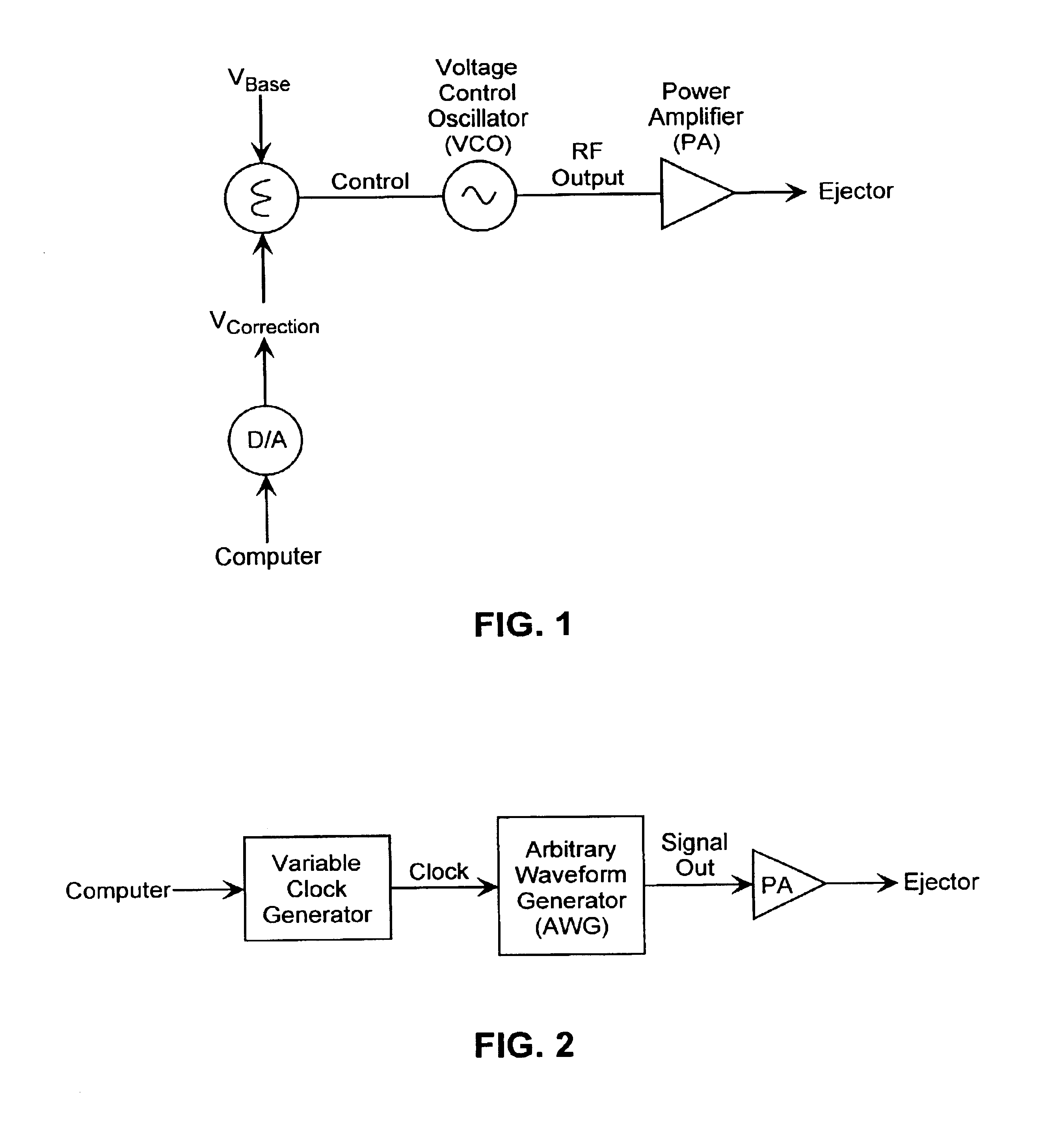
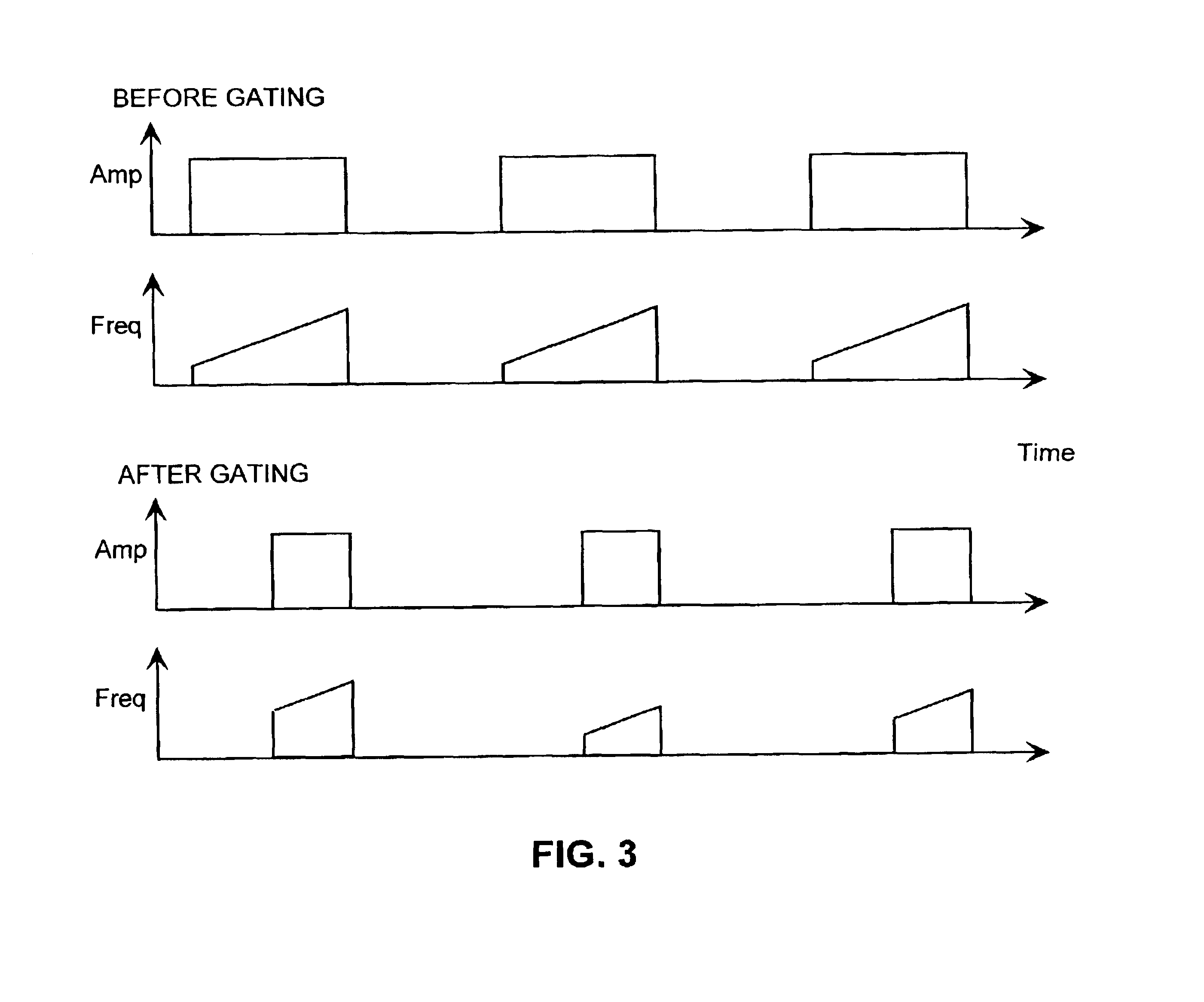
  • Frequency correction for drop size control
  • Frequency correction for drop size control
  • Frequency correction for drop size control

Examples


Embodiment Construction

Definitions:

[0015]Before describing the present invention in detail, it is to be understood that this invention is not limited to specific fluids, biomolecules or device structures, as such may vary. It is also to be understood that the terminology used herein is for the purpose of describing particular embodiments only, and is not intended to be limiting.

[0016]It must be noted that, as used in this specification and the appended claims, the singular forms “a,”“an” and “the” include plural referents unless the context clearly dictates otherwise. Thus, for example, reference to “a reservoir” includes a plurality of reservoirs, reference to “a fluid” includes a plurality of fluids, reference to “a biomolecule” includes a combination of biomolecules, and the like.

[0017]In describing and claiming the present invention, the following terminology will be used in accordance with the definitions set out below.

[0018]The terms “acoustic coupling” and “acoustically coupled” used herein refer t...


PUM


Abstract

The present invention provides a method and device for the acoustic ejection of fluid droplets having a constant drop size from fluid-containing reservoirs having varying fluid heights contained therein without the need for repositioning the acoustic ejector in the z direction by adjusting the RF frequency and amplitude. In one embodiment, the device is comprised of: a plurality of reservoirs each adapted to contain a fluid; an ejector comprising a means for generating acoustic radiation, means for controlling the RF frequency and amplitude used to generate the acoustic radiation, means for focusing the acoustic radiation at a focal point near the fluid surface in each of the reservoirs; and a means for positioning the ejector in acoustically coupled relationship to each of the reservoirs. The invention is useful in a number of contexts, particularly in the preparation of biomolecular arrays.

Description

TECHNICAL FIELD[0001]This invention relates generally to the use of focused acoustic energy in the ejection of fluids, and more particularly relates to methods for controlling the size and velocity of droplets ejected.BACKGROUND[0002]A number of patents have described the use of acoustic energy in droplet ejection. For example, U.S. Pat. No. 4,308,547 to Lovelady et al. describes a liquid drop emitter that utilizes acoustic principles in ejecting liquid from a body of liquid onto a moving document for forming characters or bar codes thereon. Lovelady et al. is directed to a nozzleless inkjet printing apparatus wherein controlled drops of ink are propelled by an acoustical force produced by a curved transducer at or below the surface of the ink.[0003]The Lovelady et al. patent makes use of a piezoelectric shell transducer to both generate and focus the acoustic energy. Several other methods have also been developed to focus the generated acoustic energy and eject a droplet of liquid....

Claims


Application Information

Patent Timeline
Patent Type & Authority Patents(United States)
IPC IPC(8): B41J2/05
CPCB41J2/04573B41J2/04591B41J2/04575
Inventor HADIMIOGLU, BABURELLSON, RICHARD N.
Owner LABCYTE
Learn More