Faraday flashlight

a flashlight and flashlight body technology, applied in the field of human-powered flashlights, can solve the problems of internal external integrity breach, eventual breach of sealing integrity, and light bulb change, and achieve the effects of saving mechanical energy, facilitating manual movement of the flashlight body, and conserving the residual momentum of the magn

Inactive Publication Date: 2005-05-17
CRICKET HLDG FAR EAST
View PDF25 Cites 20 Cited by
  • Summary
  • Abstract
  • Description
  • Claims
  • Application Information

AI Technical Summary

Benefits of technology

[0010]The light generating device of the present invention utilizes a large centrally located magnet which is mounted to slide past a magnet pickup or current induction wire which may be preferably mounted at a center point of travel in a tubular housing having a tubular chamber through which the magnet travels. A pair of elastomeric bumpers are located each at the end of the tubular chamber. Each of the elastomeric bumpers are supported by its own spring secured against the sides, end or both of the terminal ends of the tubular chamber. The mounting sequence is first chamber end or structure to first spring, to first bumper to freely slidable or translatable magnet to second bumper secured by second end or structure of the chamber. The result is a device which both facilitates the manual movement of the flashlight body so that the magnet slides past the center magnet pickup or current induction wire, and also conserves the residual momentum of the magnet once it has traveled past the magnet pickup or current induction wire by providing a bumper and spring to conserve some of the mechanical energy going in the other direction.
[0011]Where the size of the magnet is matched to the length of the tubular chamber and the size of the springs, a matched, sealed mechanical system is formed which can be continuously operated with minimal wrist energy. The mechanical input energy is intended to be stored regardless of whether the light is operational during charging or not. The energy consumption of the lamp should be such that the mechanical charging action can keep sufficient energy stored in advance of its consumption in light production so that the flashlight of the invention can be continued to be utilized even when any temporary store of energy provided is depleted. This action is contemplated to be performed by shaking the flashlight several times to input mechanical and then electrical energy into storage, followed by a period of illumination from an energy reservoir, which may be chemical or capacitor or other.
[0012]In addition, an activation switch for external control is had with an external smaller magnet which operates in conjunction with a reed switch to enable mechanical activation without the necessity to form a mechanical linkage between the inside and outside of the flashlight.
[0013]One appliance which can greatly expand the capabilities of the flashlight of the invention is a charger which uses inductive energy transfer. Ordinary chargers rely upon physical touching of contacts and the corresponding external corrosion possibilities, as well as the possibility of non-contact with the outside energy source. Because the flashlight of the invention is completely sealed, inductive charging offers secure charging and no possibility of lack of charge through loss of physical contact.
[0015]The charger uses an induction system which has a physical realization matching the coil used in the charging system of the flashlight. Proximity to the charger, and its charging coil or proximity to the electromagnetic field produced by the charger will result in charging. As a result, the structure of the charger is not particularly constrained. A wall plug-in unit which is supported by an outlet and which further supports the flashlight is preferred, but a modular charger which has a wall transformer and a connected sleeve would also work well. The former enables deployment at various outlets in a room, while the latter enables more specialized orientation and deployment.
[0016]The flashlight of this invention is further enhanced by the independently utilizable options including (1) addition of a secondary brighter LED and (2) the addition batteries housed in a detachable battery compartment. The batteries serve to power the secondary brighter LED or two LEDs together upon activation of a secondary switch. This is to increase brightness of this invention. The batteries also serve to act as a one time quick charger for the main capacitor storage unit upon activation of a turbo charge switch. The turbo charge function is used to to reduce the number of shakes required to fully charge the capacitor so that the LED will able to be activated almost instantly, especially when the flashlight is not left on continuous charge. The slide knob disclosed herein can implement the turbo charge function.

Problems solved by technology

The disadvantages of conventional flashlights with this conventional configuration are generally (1) breach of internal external integrity from having to access the battery compartment fairly regularly to replace batteries, and (2) other breaches of external integrity associated with light bulb changes at the front of the device and from a mechanical linkage relating to the on and off switch.
However, when these structures are employed at points likely to be repeatedly accessed, such as the rear entrance to the battery compartment, degradation will likely occur resulting in an eventual breach of sealing integrity.
Other step have been taken to insure integrity such as placing a flexible push button cover over the on and off switch, but these covers tend to either leak early in their functional life at the ring of circular attachment, or later in their functional life by cracking or punching breach.
In some cases a crank generator is provided with the crank extending through the housing, creating another source of housing fluid breach.
The generator is itself a complex mechanical machine and also prone to water damage, rust, and excessive wear.
Because of the breakdowns cited above, non-battery flashlights are generally unreliable as an emergency or long storage time period source of lighting, and particularly in a harsh or moist environment.
Further, the majority of personal lighting products are generally inefficient as being operated using an incandescent (heated filament) light source which is not conserving of energy usage per unit of illumination.

Method used


Image

  • Faraday flashlight
  • Faraday flashlight
  • Faraday flashlight

Examples


Embodiment Construction

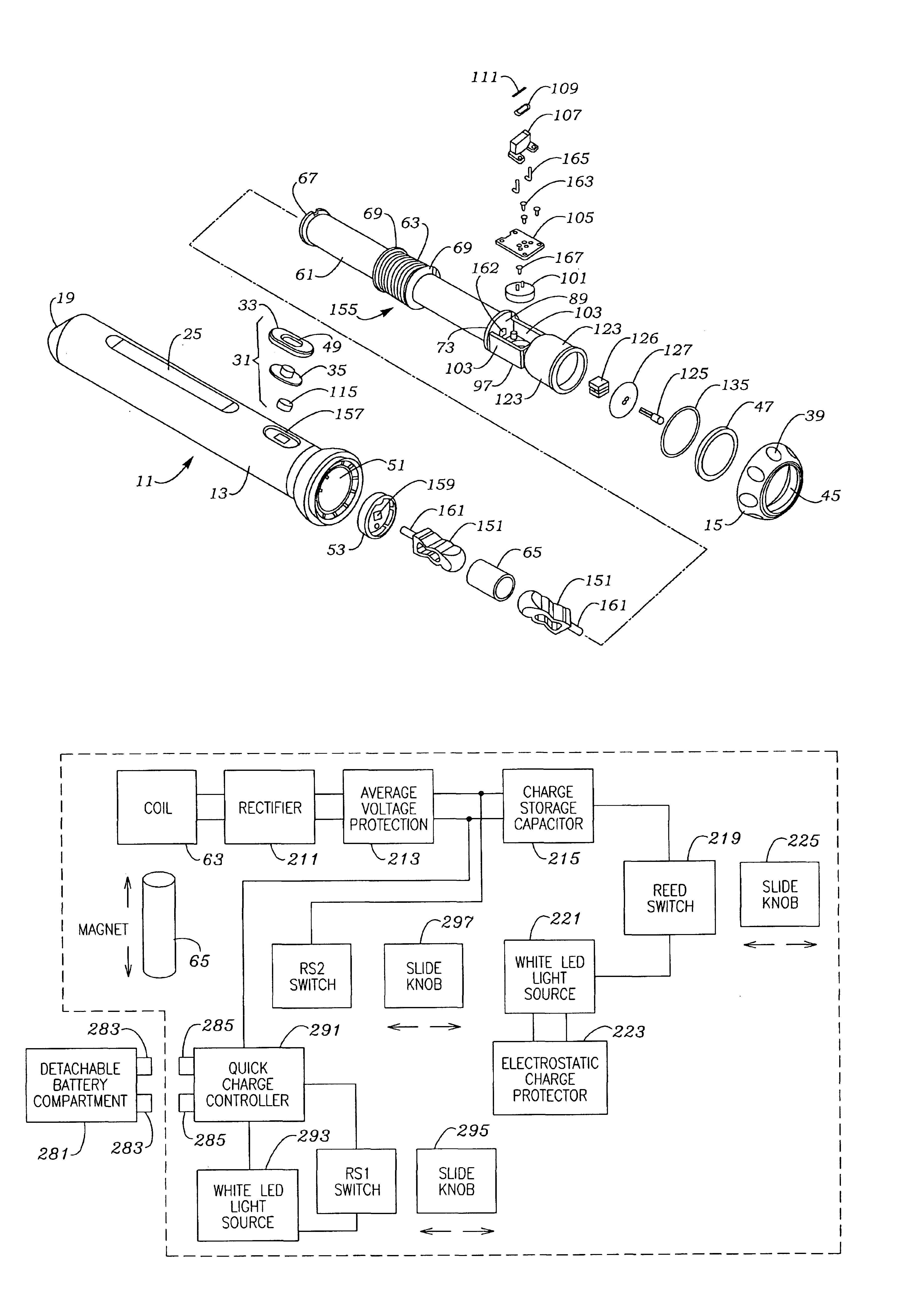
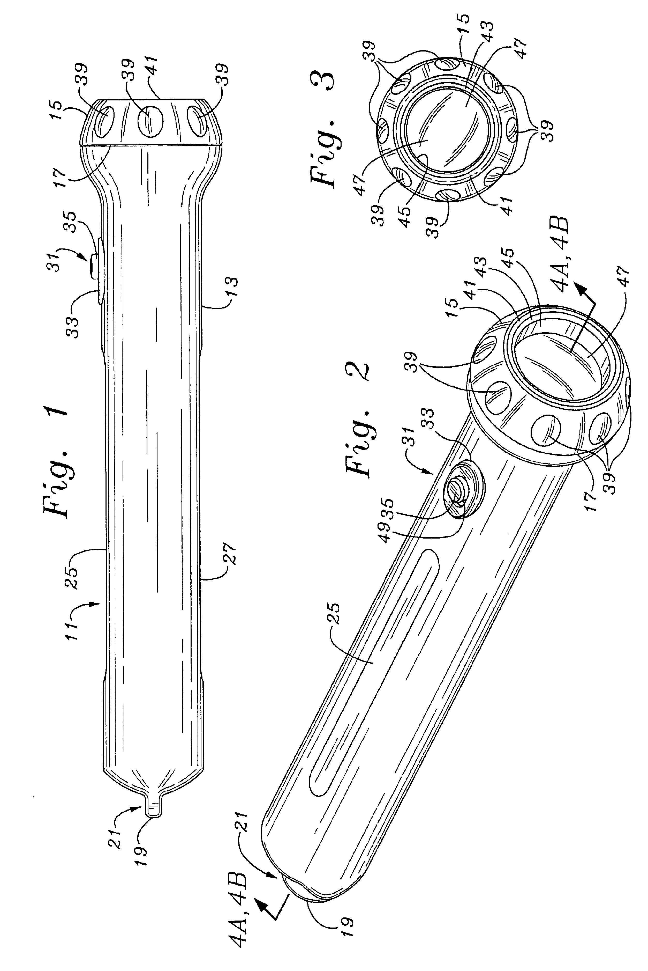
[0033]The description and operation of the invention will be best initiated with reference to FIG. 1 and which illustrates a Faraday flashlight which will hereinafter be referred to as a flashlight 11. The external appearance of the flashlight 11 discloses two portions, a main housing chamber 13 portion and a front cap 15 portion which is separated from the main housing chamber 13 portion by a dividing line 17. Front cap 15 portion may include a combination or unitary clear cap which includes a threaded engagement portion and integral lens. In the version shown in the figures, a lens will be shown to be separate from the engagement portion of the cap, but this is just one possible variation. At the rear of the main housing chamber 13 is a protruding lug 19 having an opening 21 which is not immediately visible in FIG. 2, but which is indicated by arrow. An upper flattened portion 25 and a lower flattened portion 27 are seen in FIG. 2. An expanded portion 29 of the main housing chambe...


PUM


Abstract

A light generating flashlight system device utilizes a large centrally located magnet which is mounted to slide past a magnet pickup or current induction wire which may be preferably mounted at a center point of travel in a tubular housing having a tubular chamber through which the magnet travels. A pair of elastomeric dampers are located each at the end of a support system sleeve which is sized to fit within a main housing to stabilize all internal support within a sealed unit. The result is a device which both facilitates the manual movement of the flashlight body so that the magnet slides past the center magnet pickup or current induction wire, and also conserves the residual momentum of the magnet once it has traveled past the magnet pickup or current induction wire by providing a bumper and spring to conserve some of the mechanical energy going in the other direction. Ninety second of manual activation enables about five minutes of illumination. A ready charger is disclosed which uses induction to charge the flashlight system by proximity to the manual charging magnet wire.

Description

[0001]This is a continuation-in-part of co-pending U.S. patent application Ser. No. 10 / 392,657 filed Mar. 19, 2003, which is a continuation-in-part of co-pending U.S. patent application Ser. No. 10 / 112,848 filed Mar. 29, 2002.FIELD OF THE INVENTION[0002]The present invention relates to improvements in the technology relating to inexpensive and reliable lighting sources and more particularly to a human powered flashlight free of batteries and free of external integrity breaches and which is engineered to use light efficiently.BACKGROUND OF THE INVENTION[0003]Production of light with a portable light source or flashlight is a well known expedient in which a tubular body is fitted with a number of series connected batteries. The disadvantages of conventional flashlights with this conventional configuration are generally (1) breach of internal external integrity from having to access the battery compartment fairly regularly to replace batteries, and (2) other breaches of external integr...

Claims


Application Information

Patent Timeline
Patent Type & Authority Patents(United States)
IPC IPC(8): F21L13/00F21L13/06H02K35/02H02K35/00
CPCF21L13/06F21V31/00H02K35/02H02J7/025F21Y2101/02F21Y2115/10H02J7/0045H02J50/10
Inventor MAH, PAT Y.
Owner CRICKET HLDG FAR EAST
Why Eureka
Try Eureka