Metallic article with integral end band under compression

a technology of end band and metal plate, applied in the field of metal plates, can solve problems such as separation or cracks starting in the blade tip

Inactive Publication Date: 2005-05-17
GENERAL ELECTRIC CO
View PDF11 Cites 24 Cited by
  • Summary
  • Abstract
  • Description
  • Claims
  • Application Information

AI Technical Summary

Problems solved by technology

Such stresses have developed to an extent that can result in the generation of separations or c

Method used


Image

  • Metallic article with integral end band under compression
  • Metallic article with integral end band under compression

Examples


Embodiment Construction

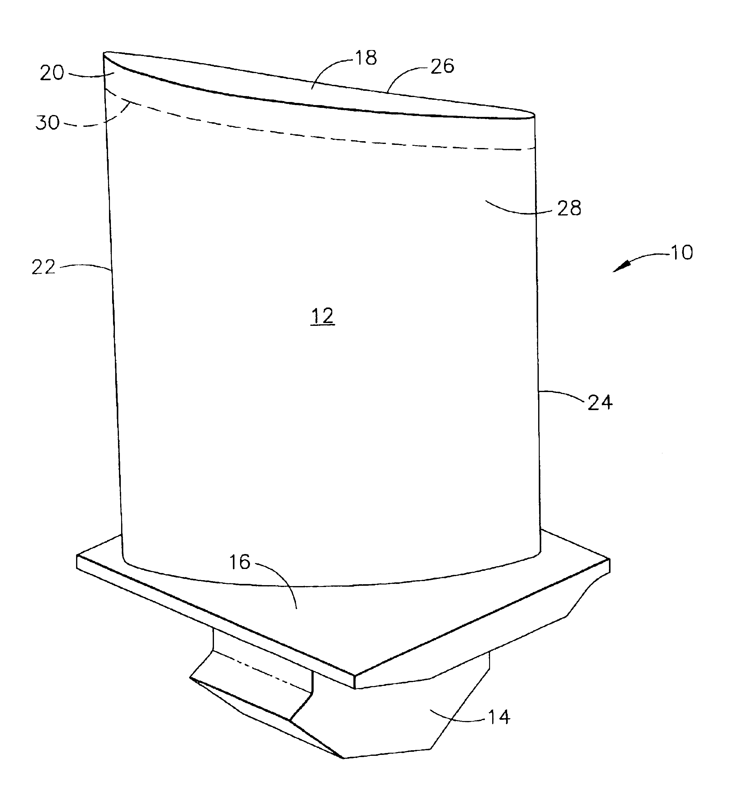
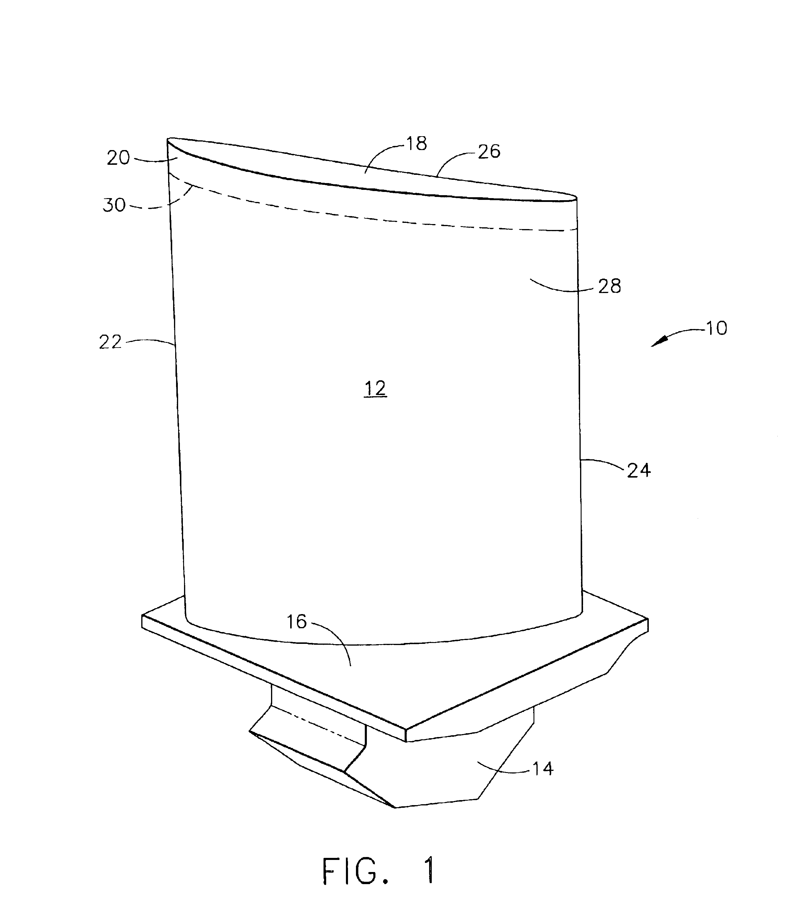
[0009]Blades in turbomachinery experience vibration that can lead to cracks and separation of surfaces of the blades. Such surfaces include the edge portions of airfoils such as the leading edge, the trailing edge, and the airfoil tip. Improving the fatigue strength of the material from which the blade is made can reduce the probability of cracks forming and propagating into the blade to failure. The radial outer tips of rotating blades are subject to the above described type of operational damage, not only from the conditions of operation but also from the potential of rubbing with opposing, cooperating components during service operation. The potential depth of such operational damage has been determined for this invention by inspecting damage to service operated blades. In some cases, the depth of such damage has extended up to about a nominal 0.1″ from the tip into and toward the blade airfoil. Tip rubs can degrade the material fatigue strength in the rub-damaged region. Residua...


PUM

PropertyMeasurementUnit
Fractionaaaaaaaaaa
Lengthaaaaaaaaaa
Depthaaaaaaaaaa

Abstract

An article made of a metallic material and comprising a body and a body end portion integral with the body, includes a band of the metallic material at the end portion substantially through the entire end portion, the band being under a compressive stress greater than the body. An example of the article is a turbine engine balding member in which the body is the airfoil of the member and the band is disposed at the radially outer tip portion of the airfoil. One method for providing the band includes performing roller deformation on the end portion until a desired amount of compressive stress is developed in the band substantially through the entire end portion.

Description

[0001]This application is a divisional of Ser. No. 09 / 627,143, filed on Jul. 27, 2000, now U.S. Pat. No. 6,672,838, and claims benefit theretoBACKGROUND OF THE INVENTION[0002]This invention relates to a metallic article including an integral end or tip portion subject to damage such as cracking. More particularly, it relates to a metallic article, for example a gas turbine engine blading member made of a metallic alloy, including a tip subject to tip separation or cracking during operation and propagation of such damage from the tip into underlying material.[0003]Power generation apparatus such as turbine engines include blading members, for example blades and vanes, having a free end portion or tip disposed in juxtaposition with another component in a relatively moving or rotating relationship. Examples of such members include a rotating compressor blade and a rotating turbine blade, having an airfoil with an airfoil tip disposed opposite a stationary shroud or seal across a relati...

Claims


Application Information

Patent Timeline
IPC IPC(8): B24B39/00B23P9/00B23P9/02C21D7/04C21D7/00F01D5/14F01D5/20F01D5/28F02C7/00F04D29/38
CPCB23P9/02B24B39/00C21D7/04F01D5/20F01D5/286Y10T29/49336C21D2221/02C21D2221/01
Inventor CRALL, DAVID WILLIAMLINKO, III, PETER JOHN
Owner GENERAL ELECTRIC CO
Why Eureka
Try Eureka