Clamping device for injection-molding machine

a technology of injection molding machine and clamping device, which is applied in the direction of dough shaping, manufacturing tools, food shaping, etc., can solve the problems of screw rods taking more time to complete the closing of molds, flashing, and molded products with flashes or inferior quality, etc., and wasting energy

Inactive Publication Date: 2005-05-17
IND TECH RES INST
View PDF3 Cites 8 Cited by
  • Summary
  • Abstract
  • Description
  • Claims
  • Application Information

AI Technical Summary

Benefits of technology

[0010]Another object of the present invention is to provide a clamping device in which the lead of a screw rod can be varied, so that the screw rod moving in large lead enables closing of mold at high speed, and the screw rod moving in small lead enables production of high-pressure clamping force in an injection-molding machine.
[0020]Thus, the high-speed screw rod unit, which is a large-lead screw rod having a large pitch, would move rapidly at an initial stage in the course of closing mold to enter the state of closing mold without wasting valuable time. At this point, since the braking unit is not actuated, and the clamping screw rod unit applies a pre-pressure to the nut element via the pre-pressing unit to rotate along with the nut element instead of rotating alone, the high-speed screw rod unit is allowed to move forward at high speed.
[0021]The high-speed screw rod unit having large pitch would have an acting force with low rate of amplification, preventing the high-speed screw rod unit from producing a required clamping force during closing mold. By actuating the braking unit at this point to brake the nut element, the driving torsion produced by the driving source is concentrated on the clamping screw rod unit and continuously increased to finally become larger than the pre-pressure applied by the clamping screw rod unit to the nut element, and thereby causes the clamping screw rod unit to rotate relative to the braked nut element.
[0025]To open the mold, the nut element is released from the braking unit, and the driving source is caused to rotate reversely for the clamping screw rod unit to release the mold from the high-pressure clamping force, so that the high-speed screw rod unit can move the movable mold holder and the first mold half backward to open the mold at high speed.

Problems solved by technology

Due to the small clamping force, many problems, such as flashing, molded products with flashes or inferior quality, etc., would occur.
However, the screw rod would take more time to complete the closing of mold.
However, a high-power servomotor consumes extremely high power and has a big volume to result in waste of energy, increased equipment cost, and occupation of large space.
It is therefore an important and critical issue to develop a power-driven clamping device for injection molding machine that enables closing of mold at high speed and under high-pressure clamping force with a low-power driving source.

Method used


Image

  • Clamping device for injection-molding machine
  • Clamping device for injection-molding machine
  • Clamping device for injection-molding machine

Examples


Embodiment Construction

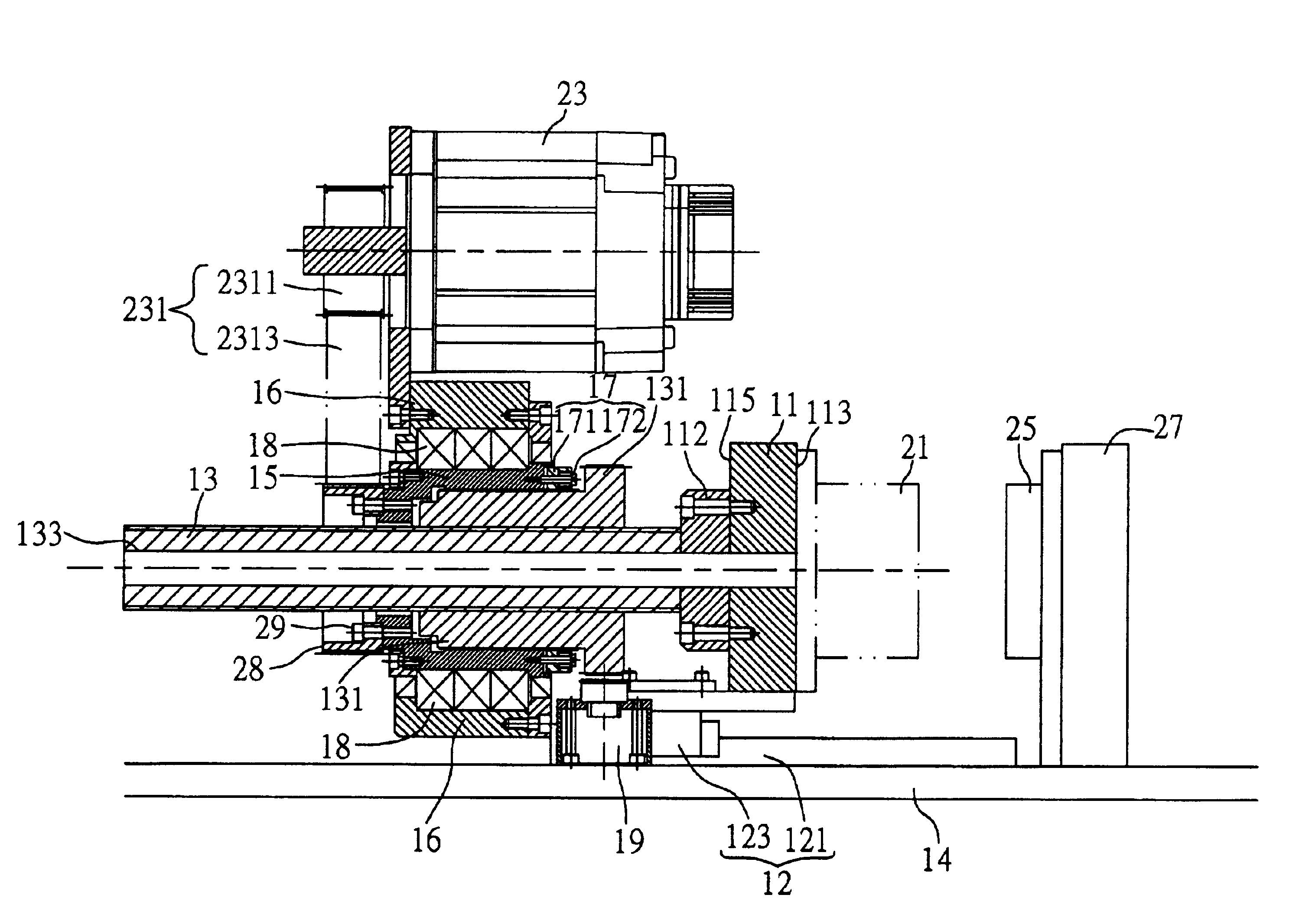
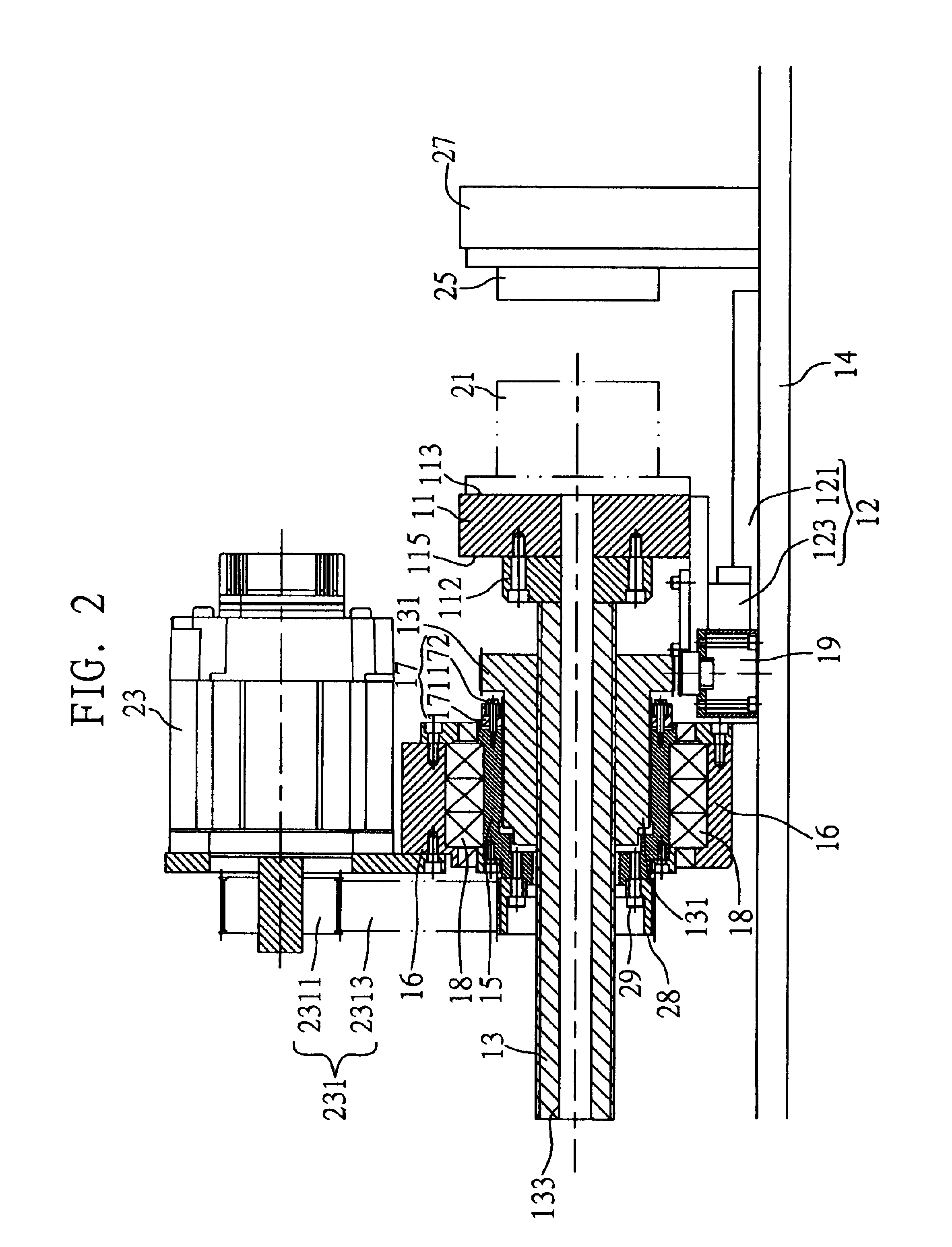
[0037]An embodiment of the clamping device for injection-molding machine according to the present invention will now be described with reference to FIGS. 2 to 6. The clamping device for injection-molding machine according to the present invention mainly includes a movable mold holder 11, a guiding assembly 12, a high-speed screw rod unit 13, a clamping screw rod unit 15, a transmission assembly 231, a pre-pressing unit 17, and a braking unit 19.

[0038]For the purpose of simplification and clarity, only parts and elements of the injection-molding machine that are related to the clamping device are shown in the drawings and denoted with reference numerals. Since the injection-molding machine is a known art, it is not illustrated in details in the drawings.

[0039]Please refer to FIGS. 2 to 4. The movable mold holder 11 is connected at a first side 113 to a first mold half 21. The guiding assembly 12 is mounted on a bed 14 of the injection-molding machine and includes a slide rail 121 and...


PUM

PropertyMeasurementUnit
pre-pressureaaaaaaaaaa
clamping forceaaaaaaaaaa
pressureaaaaaaaaaa

Abstract

A clamping device for injection-molding machine includes a high-speed screw rod unit having a nut element screwed thereto and a movable mold holder connected to a front end thereof, a clamping screw rod unit screwed to a rear end of the nut element and connected to a transmission assembly, a pre-pressing unit adjustably tightened to the clamping screw rod unit for the latter to generate a pre-pressure against the nut element, and a braking unit adapted to brake the nut element. When the nut element is not braked, the high-speed screw rod unit is driven by the transmission assembly to move forward at high speed for closing mold. And, when the nut element is braked and the clamping screw rod unit is driven by the transmission assembly to rotate relative to the nut element, the nut element is linearly pushed forward to generate a high-pressure clamping force during closing mold.

Description

BACKGROUND OF THE INVENTION[0001]The present invention relates to a clamping device for injection-molding machine, and more particularly to a clamping device for injection-molding machine including a high-speed screw rod unit, a lead of which can be changed to enable closing of mold at a high speed and producing of a high-pressure clamping force for closing mold.[0002]The clamping device is one of many critical parts in an injection-molding machine to ensure reliable closing of mold. Since molten material is supplied into a mold cavity under a extremely high pressure, it is necessary to apply a sufficient clamping force to tightly close the mold to avoid flashing, molded products with flashes, or other conditions that would adversely affect the quality of the molded products.[0003]In closing the mold, it is desirable the clamping device is moved at a high speed to save time, and provides a sufficient clamping force at the time two mold halves of the mold contact with each other in o...

Claims


Application Information

Patent Timeline
Patent Type & Authority Patents(United States)
IPC IPC(8): B29C45/66
CPCB29C45/66
Inventor TENG, MING-CHANGCHUNG, HSIANG-NIENFENG, WEN-HUNGCHEN, MING-CHI
Owner IND TECH RES INST
Why Eureka
Try Eureka