Coaxial cables, multicore cables, and electronic apparatuses using such cables

a technology of coaxial cables and coaxial cables, which is applied in the direction of power cables, cables, insulated conductors, etc., can solve the problems of troublesome removal of outer conductors, serious problems, and decrease the dielectric strength of the insulation layer, so as to increase the demand for further downsizing, increase the noise of production, and reduce the effect of production costs

Inactive Publication Date: 2005-05-17
SUMITOMO ELECTRIC IND LTD
View PDF19 Cites 13 Cited by
  • Summary
  • Abstract
  • Description
  • Claims
  • Application Information

AI Technical Summary

Benefits of technology

[0024]The invention will be described with reference to the accompanying drawings. The coaxial element wire constituting the coaxial cable of the present invention basically has an insulation layer with a thickness of 0.15 mm or less, and hence, the coaxial element wire can be made smaller in diameter. Accordingly, positive effects of the invention are exhibited especially when it is applied to a coaxial cable or a thin flat type multicore cable for use in wiring in an electronic apparatus which has a small space for wiring and hence requires a decrease in the volume of wires and cables occupying the space.
[0025]Further, the coaxial element wire is constructed by using as the outer conductor a ribbon-shaped conductor obtained by pressing and flattening a copper or copper alloy round wire and helically wrapping the ribbon-shaped conductor around the insulation layer. FIG. 1 is a perspective view schematically showing a single-core coaxial cable employing a typical coaxial element wire of the present invention. Referring to FIG. 1, reference numeral 1 denotes a center conductor of copper, copper alloy, or the like, 2 denotes an insulation layer made of PFA, polyester, polyimide film, or the like, 3 denotes a ribbon-shaped conductor as an outer conductor whose cross-section is virtually a rectangle having its four corners smoothed, and 4 is an outer jacket. The ribbon-shaped conductor 3 can be produced by such a method as chamfering four corners of a rectangular conductor. It can also be manufactured by pressing and flattening a copper or copper alloy round wire, which is advantageous in terms of production cost. The ribbon-shaped conductor is helically wrapped around the insulation layer 2 to provide the outer conductor. In FIG. 1, the combination of the center conductor 1, insulation layer 2, and outer conductor 3 is labeled with reference number 5.
[0026](1) Thickness of the insulation layer: Since the setting position or angle of electronic apparatuses such as notebook computers and sensors for medical purposes are manually changed, there are increasing demands for further downsized and light weight apparatuses. Hence, narrower coaxial cables are being demanded. When a coaxial cable is deformed by rotation or bending of a portion of a device in which it is disposed, strain is imposed on the coaxial cable, especially on its outer conductor, and such strain becomes greater, accompanied by an increase in produced noises, with the increase of the outer diameter. Therefore, the insulation layer 2 and the coaxial element wire constituting the coaxial cable of the invention are required to have a thickness as thin as 0.15 mm or less. While it is preferred that the insulation layer 2 thickness be as small as possible, since it is subjected to deformation by repeated bending or torsion during the service period, it is desired that it be given a thickness of, for example, 0.3 mm or more, which is considered to be the minimum value when mechanical strength and flexibility are taken into account.
[0027](2) Outer conductor: The ribbon-shaped conductor 3, which is formed by pressing and flattening a round wire made of a metal, such as copper, copper alloy, or the like, is helically wrapped around the insulation layer 2 to form the outer conductor.
[0028]Since such a ribbon-shaped conductor 3 is obtained by pressing a round wire, the cross section thereof has a smooth form at the four corners, and takes on virtually a retangular form not having any acute edge all along the circumference. The outer conductor is constructed by wrapping the ribbon-shaped conductor 3 around the insulation layer 2 with one long side of the virtually rectangular form facing the insulation layer 2. Because the ribbon-shaped conductor 3 has such a form, it can be provided free from an acute edge as was produced in the slit tape in the conventional art and, therefore, injury to the insulation layer 2 or localization of voltage rarely occurs so that a stabilized insulating withstand-voltage characteristic can be obtained. Further, since a round wire made of copper or copper alloy is pressed and flattened to be used as the ribbon-shaped conductor 3 without annealing, a merit can be obtained such that the ribbon-shaped conductor 3 can be wrapped up so as not to become loose, without the need for braiding as was practiced in the method of the conventional art. When wrapping the ribbon-shaped conductor 3, it must be kept under a tension not impairing the characteristic of the insulation layer 2, while enabling the wrapped up ribbon-shaped conductor to constantly fasten the insulation layer 2, and under such a tension that will not cause the coaxial elemement wire or the coaxial cable to be damaged when the same is bent or twisted. It is preferred that the tension be not smaller than 30% and not greater than 80% of the tensile strength of the ribbon-shaped conductor 3. Further, a layer obtained by depositing a metal on a thin tape may be disposed under the outer conductor. Then, both an improvement in the shielding effect and an increase in the insulating withstand-voltage of the insulation layer 2 can be attained.
[0029]The wrapping angle (Φ)) of the ribbon-shaped conductor 3 is preferably 45 degrees or more for providing flexibility. (The wrapping angle Φ) is illustrated in FIG. 2(A)(2).) While it is more preferably 60 degrees or more, if it is increased close to 90 degrees, the productivity is greatly decreased and it is undesirable. Therefore, the maximum limit for the wrapping angle Φ is approximately 80 degrees. As to the size of the outer conductor, it is desired that the thickness be 0.03 mm or less in order to reduce the outer diameter of the coaxial element wire and the coaxial cable and, in view of the mechanical strength, it is desired that it be not smaller than 0.01 mm. From the viewpoint of maintaining the characteristics which the outer conductor should have, it is better for the ribbon-shaped conductor 3 to have a large width, preferably 0.1 mm or more. However, from the point of view of the operability of the wrapping operation and the cost of production, one having a width of 0.3 mm or less is preferable because that small of a width is economical in material costs and allows the wrapping work to be made free of wrinkle formation. Especially from the point of view of electrical characteristics, mechinical characteristics, and workability, a tape-shaped conductor 0.025 mm thick and 0.20 mm wide manufactured by pressing a round wire of 0.08 mm in outer diameter or a tape-shaped conductor 0.012 mm thick and 0.18 mm wide manufactured by pressing a round wire of 0.05 mm in outer diameter have excellent characteristics as the outer conductor.

Problems solved by technology

On the other hand, its disadvantage is that removal of the outer conductor is troublesome when, for example, making a terminal treatment.
However, at the time of slitting the metallic tape, sharp edges such as burrs are produced on the cut surface and such edge portions can injure the insulation layer 12 or cause a voltage concentration on that portion thereby decreasing the dielectric strength of the insulation layer 12.
This problem becomes serious especially when a small-diameter coaxial cable whose insulation layer thickness is as small as 0.15 mm or less is used.
Further, when a conventional coaxial cable is used for connecting devices within an electronic apparatus, especially when it is used in a notebook computer at the rotating portion where the monitor portion and the main body portion are connected, or when it is disposed at the moving portion of a diagnostic sensor cable which moves when changing examined parts of the body, there arises a problem of electrostatic noises produced by friction between the insulation layer 12 and the outer conductor 13 of the moving coaxial cable.

Method used


Image

  • Coaxial cables, multicore cables, and electronic apparatuses using such cables
  • Coaxial cables, multicore cables, and electronic apparatuses using such cables
  • Coaxial cables, multicore cables, and electronic apparatuses using such cables

Examples


example 1

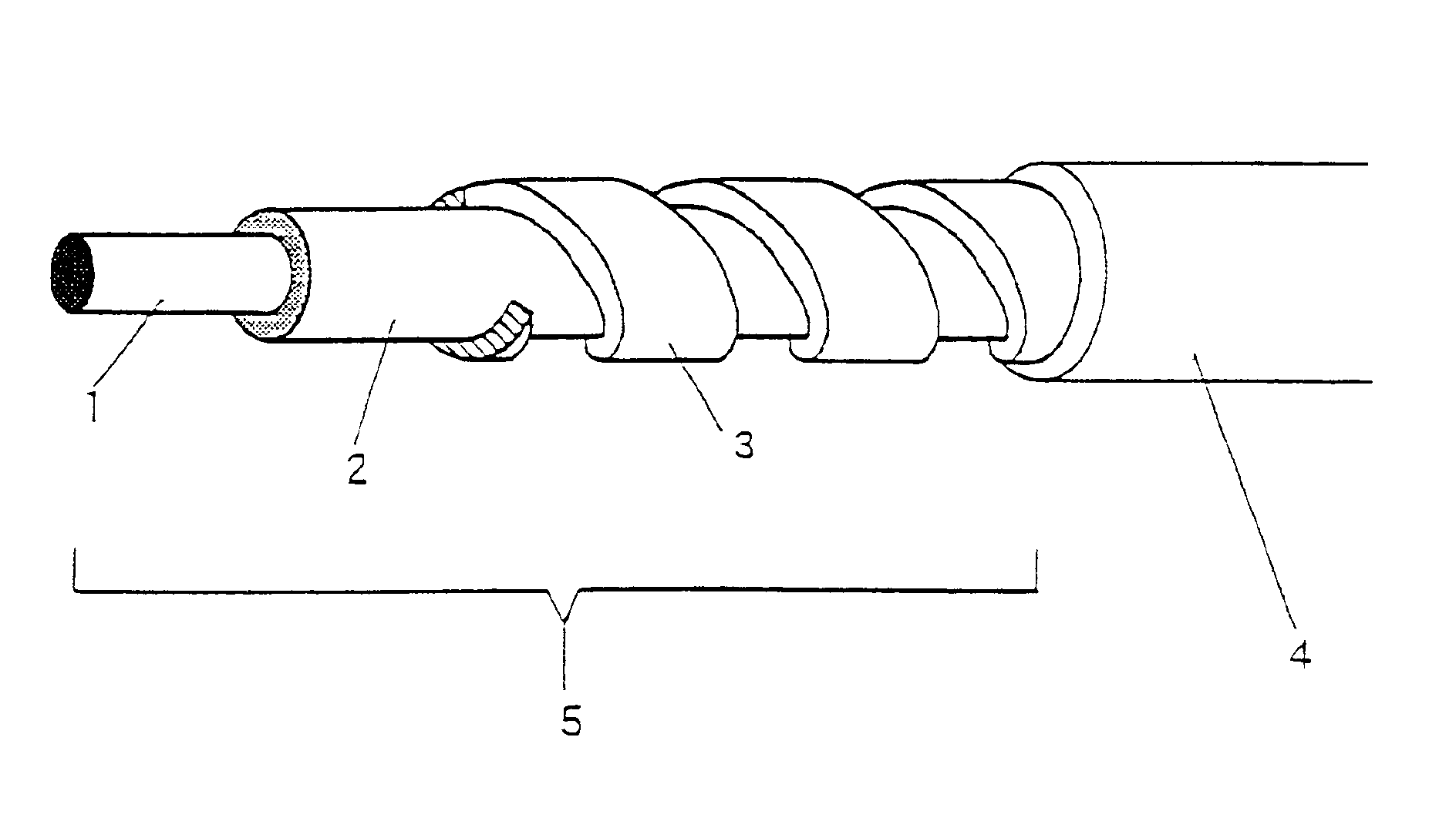
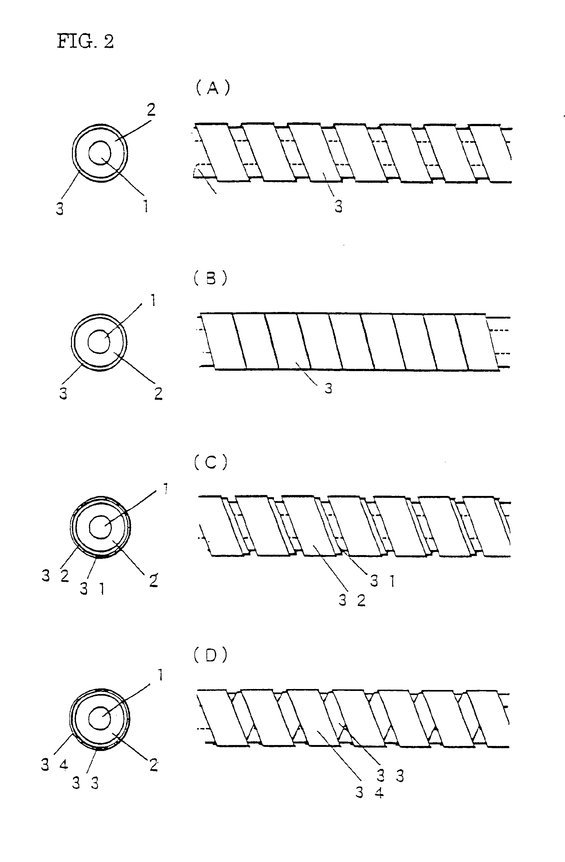
[0033]For use as the outer conductor, a tin-plated round wire 40 of a copper alloy of 0.05 mm in outer diameter having a cross section as shown in FIG. 5(A) was pressed and thereby a long ribbon-shaped conductor 42 0.012 mm thick and 0.18 mm wide having a cross section as shown in FIG. 5(B) was manufactured. As the insulation layer 2, PFA (tetrafluoroethylene-perfinoroalkylvinylether copolymer) resin was extruded to over the periphery of a center conductor 1 of 0.09 mm in outer diameter (seven tin-plate copper-alloy wires of 30 μm in outer diameter being stranded) by a known extruding and covering method so that a circular profile of 0.23 mm in outer diameter is formed. Then, the above described tape-shaped conductor (42) was helically wrapped around the same, so as to form an angle Φ of 68 degrees with respect to the axis of the coaxial element wire, by open wrapping as shown in FIGS. 2(A)(1) and 2(A)(2), spaced apart at a pitch of 0.29 mm, under a tension of 60 gf per piece. In th...

example 2

[0041]In Example 2, a coaxial element wire was produced by helical wrapping of a ribbon-shaped conductor 3 under a tension of 55 gf per piece, at a pitch of 0.18 mm, at an angle of 75 degrees, and in a butt-joined manner as shown in FIGS. 2(B)(1) and 2(B)(2). This coaxial element wire was excellent in all of the withstand voltage characteristics, bending characteristics, torsion characteristics, and electrostatic noise characteristics. Using this coaxial element wire, a single-core coaxial cable, a flat type multicore cable, and a multicore cable were produced in the same manner as in Example 1.

[0042]It was confirmed also with the thus obtained coaxial cable and multicore cables that their insulating characteristics and other characteristics are good.

example 3

[0043]In Example 3, a coaxial element wire was produced by helical wrapping of ribbon-shaped conductors 31 and 32, under a tension of 65 gf per piece, at a pitch of 0.29 mm, and at an angle of 68 degrees (double sheets were wrapped, each in open wrapping, in the same direction), as shown in FIGS. 2(C)(1) and 2(C)(2). The coaxial element wire shown in FIGS. 2(D)(1) and 2(D)(2) was also produced by wrapping ribbon-shaped conductors 33 and 34 at a pitch of 0.29 mm and at an angle of 68 degrees, with the second conductor 34 wrapped in the opposite direction from the first conductor 33. These coaxial element wires had excellent withstand voltage characteristics, bending characteristics, torsion characteristics, and electrostatic noise characteristics and especially excellent shielding characteristics of the outer conductor layer. Also by the use of these coaxial element wires, a single-core coaxial cable, a flat type multicore cable, and a multicore cable were produced in the same manner...


PUM

PropertyMeasurementUnit
thicknessaaaaaaaaaa
thicknessaaaaaaaaaa
wrapping angleaaaaaaaaaa

Abstract

A coaxial element wire includes a center conductor, an insulation layer, and an outer conductor. The insulation layer is provided around the center conductor, and it has a thickness of 0.15 mm or less. The outer conductor is a ribbon-shaped conductor obtained by pressing a copper or copper alloy round wire into a flat form, without annealing after pressing. This ribbon-shaped conductor is spirally wrapped around the insulation layer to thereby form the coaxial element wire. The coaxial element wire may be covered with a protective jacket, and plural coaxial wire elements may be joined into a common jacket to form a multicore cable.

Description

REFERENCE TO A RELATED APPLICATION[0001]This application is a continuation-in-part of application Ser. No. 09 / 445,126, filed Dec. 2, 1999 now abandoned, which is relied upon and incorporated herein by reference.FIELD OF THE INVENTION[0002]The present invention relates to single-core coaxial element wires or coaxial cables, or multicore coaxial cables which are used for the connection of a liquid crystal display within a notebook computer, or for sensor cables within a medical-purpose ultrasonic wave diagnostic apparatus, and the like, and further, relates to electronic apparatuses using the same.BACKGROUND OF THE INVENTION[0003]Coaxial cables comprising a coaxial element wire, made up of a center conductor, an insulation layer, and an outer conductor, and a jacket disposed over the coaxial element wire, are known. Included among the types of coaxial cables are a single-core cable formed by providing a single coaxial element wire with a jacket, a multicore cable formed by providing a...

Claims


Application Information

Patent Timeline
Patent Type & Authority Patents(United States)
IPC IPC(8): H01B9/02H01B9/00H01B7/18
CPCH01B11/183
Inventor YOKOI, KIYONORIMORI, AKINORIENDO, SEIJIYAMAMOTO, AKIRA
Owner SUMITOMO ELECTRIC IND LTD
Why Eureka
Try Eureka