Active vibration compensation for MRI gradient coil support to reduce acoustic noise in MRI scanners

a gradient coil and active vibration compensation technology, applied in the field of low acoustic noise mri scanner, can solve the problems of noisy acoustic noise generation, many medical patients find objectionable, and vibration of external parts, so as to reduce vibration transmission and reduce acoustic noise

Inactive Publication Date: 2005-05-17
SHARKSTONE
View PDF7 Cites 27 Cited by
  • Summary
  • Abstract
  • Description
  • Claims
  • Application Information

AI Technical Summary

Benefits of technology

[0018]A fourth aspect of the invention is directed to a suspension element for reducing acoustic noise due to vibration transmission from a gradient coil assembly to a frame of a magnetic resonance imaging device, the apparatus comprising: a C-fixture including a first support for applying forces to a support portion of the frame and a second support

Problems solved by technology

Generally, the various components of the MRI scanner represent sources and pathways of acoustic noise that can be objectionable to the patient being imaged and to the operator of the scanner.
For example, the gradient coil assembly generates loud acoustic noises, which many medical patients find objectionable.
These transmitted vibrations can cause the external parts to vibrate and thereby produce acoustic noise, which will be heard by the MRI subject and the MRI operator.
Unfortunately, there is a limit to the degree of passive attenuation achievable by use of elastomeric pads or spring isolation mounts as described.
Also,

Method used


Image

  • Active vibration compensation for MRI gradient coil support to reduce acoustic noise in MRI scanners
  • Active vibration compensation for MRI gradient coil support to reduce acoustic noise in MRI scanners
  • Active vibration compensation for MRI gradient coil support to reduce acoustic noise in MRI scanners

Examples


Embodiment Construction

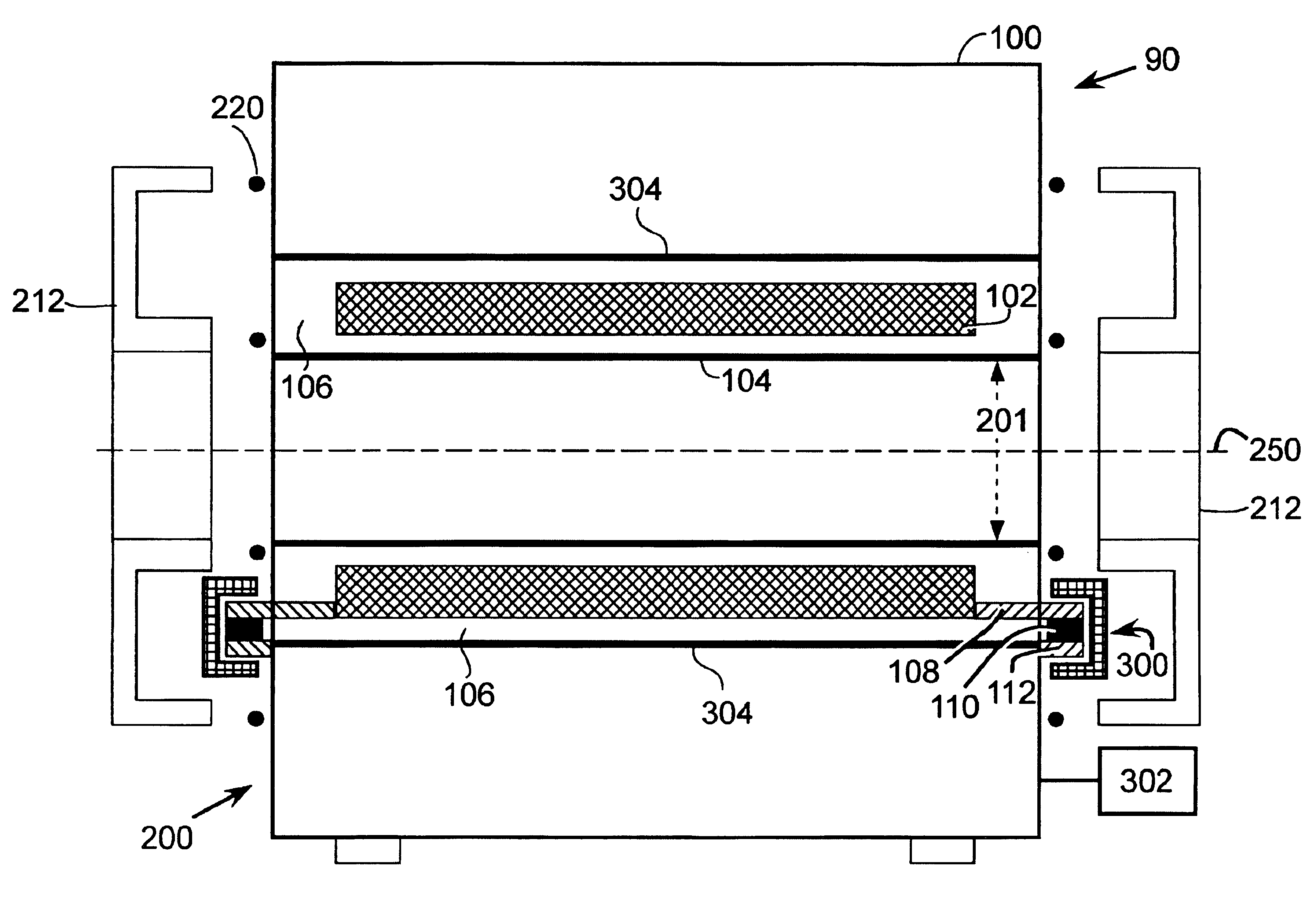
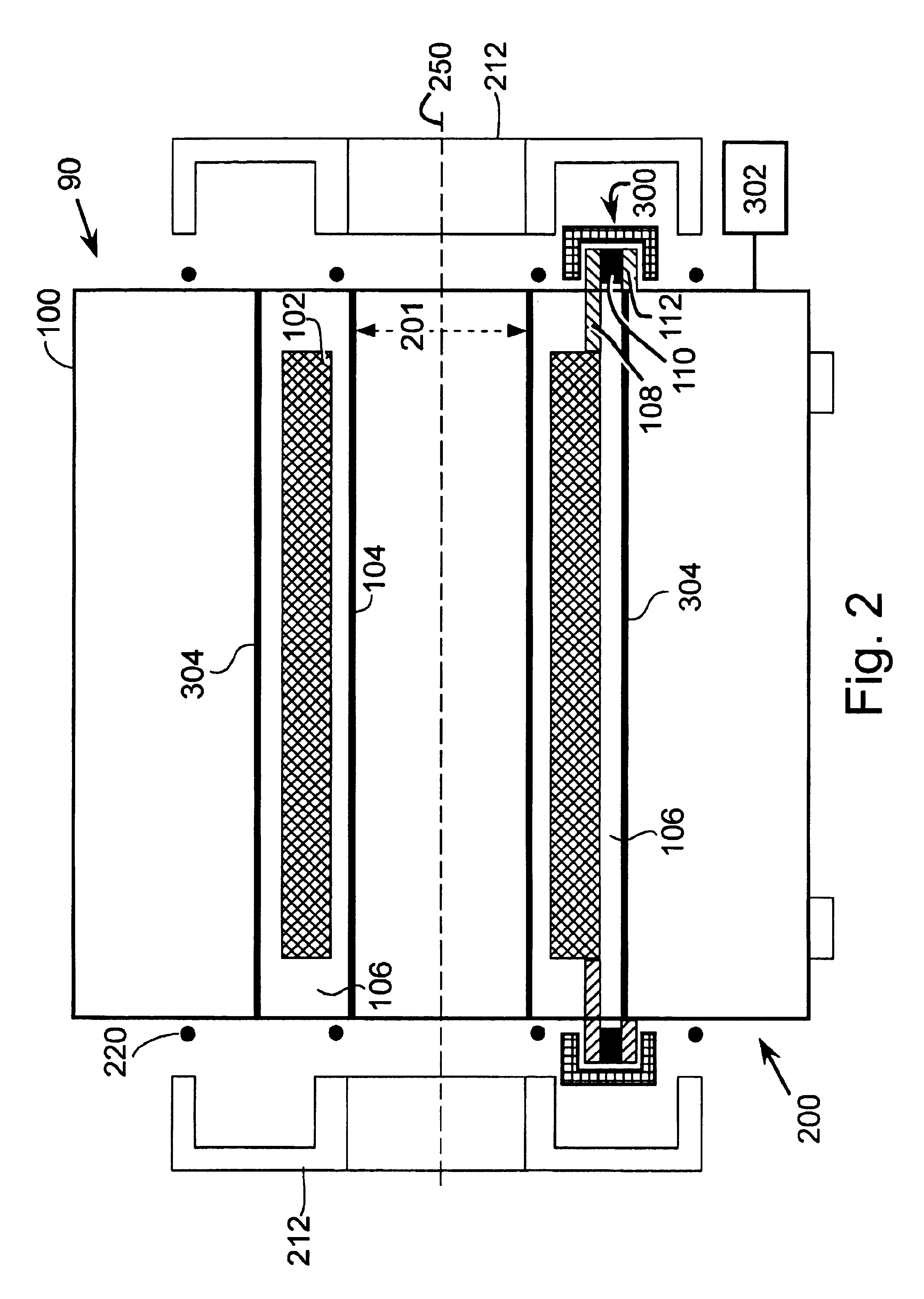
[0027]Referring to FIG. 2 there is shown an illustrative MRI device 90 to which embodiments of the present invention are applicable. MRI device 90 is of a type useful in producing magnetic resonance (MR) images of a patient or subject. Throughout the figures, like numerals represent like elements. FIGS. 2-6 show MRI device 90 based on a closed, cylindrical superconducting magnet assembly 200. It is to be appreciated by one skilled in the art that the functions and descriptions of the present invention are equally applicable to an open magnet configuration.

[0028]Referring to FIG. 2, this type of magnet assembly comprises an inner surface referred to as a magnet warm bore 304 and a cryostat shell 100 disposed radially around the outer surface. The magnet assembly further comprises end cap seals 212. When end cap seals 212 are secured against rubber gaskets 220 positioned between end cap seals 212 and cryostat shell 100, and secured against other rubber gaskets 220 positioned between e...


PUM


Abstract

The present invention provides an apparatus for reducing acoustic noise in a magnetic resonance imaging device including a suspension element including at least one resilient element and an active drivable element for applying a compensating force to reduce vibration transmission. The active drivable element is positioned so as to not directly support the weight of the gradient coil assembly, which avoids applying strong forces to relatively fragile active drivable elements, such as piezoelectric force transducers. Force signals for the active drivable element are derived in a feed-forward manner from the applied gradient waveform or from motion of the gradient coil assembly bracket. Alternatively, the active drivable element can be driven by signals derived from measured vibration or other motion of parts of the MRI magnet, gradient coils or rf coils.

Description

[0001]This application claims the benefit of U.S. Provisional Application No. 60 / 453,863, filed Mar. 12, 2003.BACKGROUND OF THE INVENTION[0002]The present invention relates generally to a magnetic resonance imaging (MRI) scanner and more particularly to a low acoustic noise MRI scanner.[0003]MRI scanners, which are used in various fields such as medical diagnostics, typically create images based on the operation of a magnet, a gradient coil assembly, and a radiofrequency coil(s). The magnet creates a uniform main magnetic field that makes unpaired nuclear spins, such as hydrogen atomic nuclei, responsive to radiofrequency excitation via the process of nuclear magnetic resonance (NMR). The gradient coil assembly imposes a series of pulsed, spatial-gradient magnetic fields upon the main magnetic field to give each point in the imaging volume a spatial identity corresponding to its unique set of magnetic fields during an imaging pulse sequence. The radiofrequency coil applies an excita...

Claims


Application Information

Patent Timeline
IPC IPC(8): G01R33/385G01R33/38
CPCG01R33/3854
Inventor EDELSTEIN, WILLIAM A.
Owner SHARKSTONE
Why Eureka
Try Eureka