
Delay locked loop having phase comparator

a phase comparator and delay lock technology, applied in the direction of oscillation comparator circuits, oscillation automatic control, instruments, etc., can solve the problems of increasing phase lock time and being unable to compensate for tracking, and achieve the effect of reducing phase lock tim

Active Publication Date: 2005-05-17
SK HYNIX INC
View PDF6 Cites 17 Cited by
  • Summary
  • Abstract
  • Description
  • Claims
  • Application Information

AI Technical Summary

Benefits of technology

The present invention aims to reduce phase lock time by performing two shift operations in one period of an external clock signal. It also compensates for tracking in phase variations by noises of an external clock signal. The delay locked loop comprises a clock buffer, delay lines, a divider, a phase comparator, a shift register, and a replica circuit. The phase comparator compares the phase of a reference clock signal with the phase of a feedback clock signal obtained by delaying the reference clock signal with the delay lines. The shift register control block controls the shift register for controlling the delay time of the delay lines, in response to the output signal from the phase comparing block, a rising clock signal synchronized with a rising edge of the external clock signal, and a falling clock signal synchronized with a falling edge thereof.

Problems solved by technology

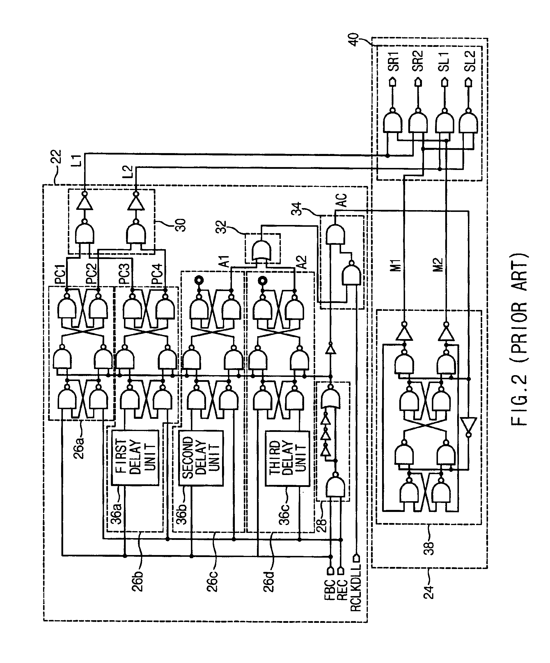
However, the clock signal generated depending on the falling edge is not used for the shift operation, which increases the phase lock time.
It is also impossible to compensate for tracking due to phase variations by noises.

Method used


Image

  • Delay locked loop having phase comparator
  • Delay locked loop having phase comparator
  • Delay locked loop having phase comparator

Examples


Embodiment Construction

[0047]A DLL having a phase comparator in accordance with a preferred embodiment of the present invention will be described in detail with reference to the accompanying drawings.

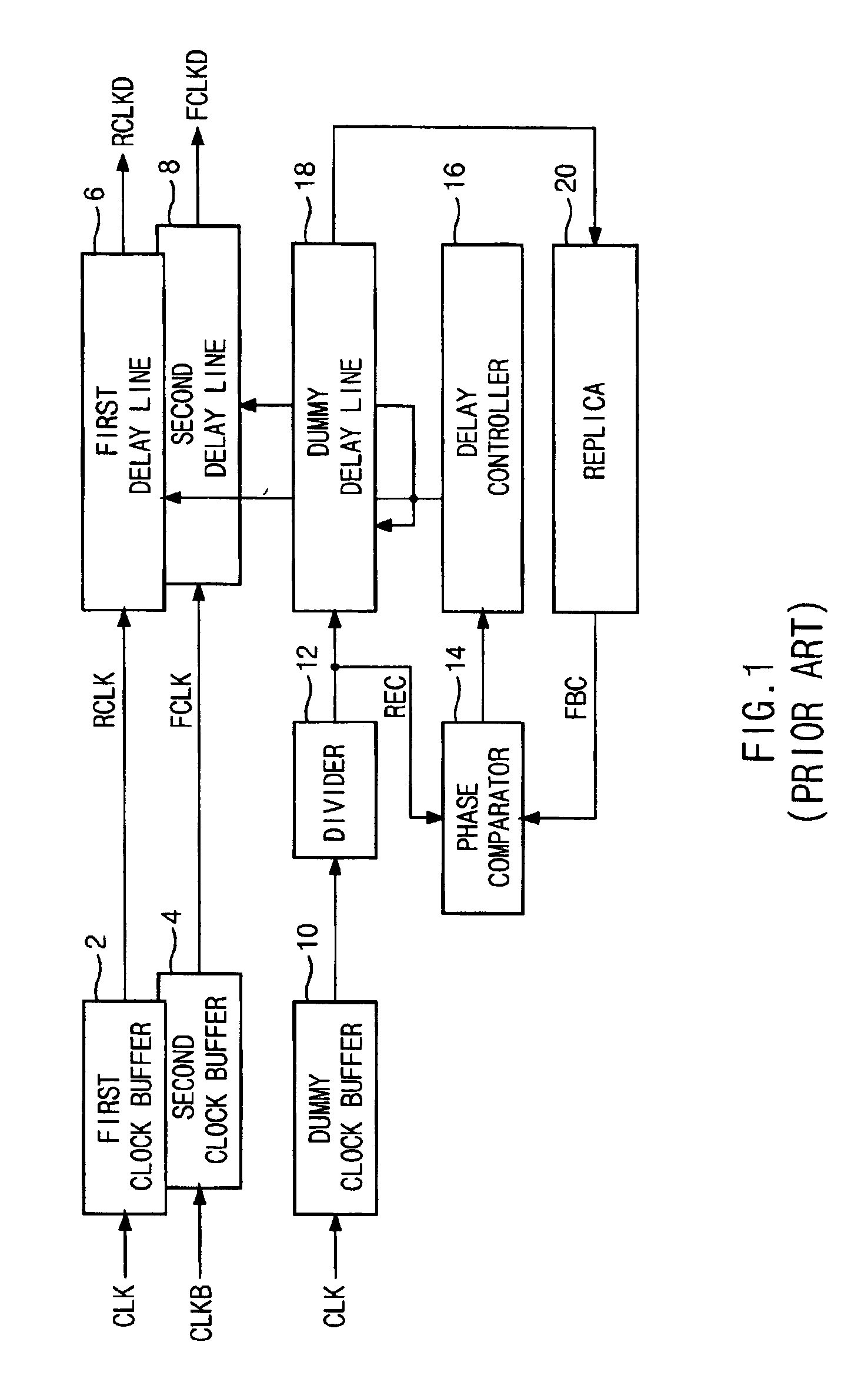
[0048]The DLL having the phase comparator compares phases of divided reference clock signal and feedback clock signal, and controls a shift register for controlling delay lines in response to not only a rising clock signal outputted from a buffer but also a falling clock signal depending on the comparison result, thereby rapidly locking an initial phase and tracking the phase in spite of fast delay variations by external noises.

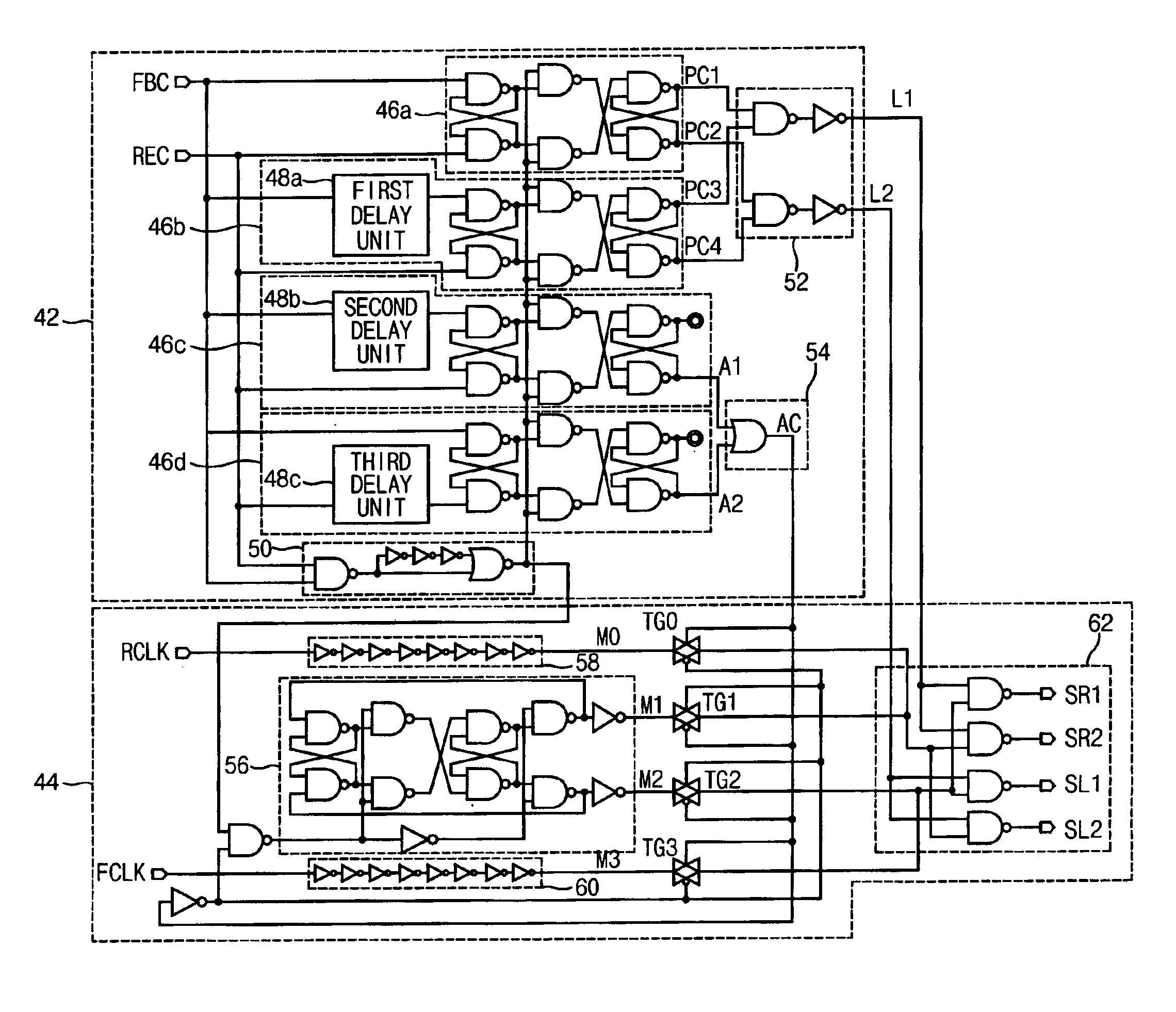
[0049]FIG. 4 is a detailed circuit diagram illustrating the phase comparator according to an embodiment of the present invention.

[0050]The phase comparator includes a comparing unit 42 for comparing a phase of a reference clock signal REC obtained by dividing a dummy clock signal outputted from a dummy clock buffer 10 by a divider 12 with a phase of a feedback clock signal FBC obtained...


PUM


Abstract

A delay locked loop features a phase comparator. The phase comparator compares a phase of a reference clock signal obtained by dividing a buffered external clock signal with a phase of a feedback clock signal considering delay time of delay lines and inside circuits, and controls a shift register for controlling the delay lines in response not only a rising clock signal outputted from a clock buffer but also a falling clock signal depending on the comparison result, thereby rapidly locking an initial phase and tracking the phase in spite of fast delay variations by external noises.

Description

BACKGROUND OF THE INVENTION[0001]1. Field of the Invention[0002]The present invention relates to a delay locked loop (hereinafter, referred to as “DLL”) having a phase comparator, and more particularly to a DLL having a phase comparator including a shift register controller for controlling a shift register of a delay line, for performing fast phase locking and phase tracking.[0003]2. Description of the Background Art[0004]In general, a DLL is a circuit for controlling external output timing of data of a dynamic random access memory (hereinafter, referred to as “DRAM”) in response to an external clock signal inputted from the outside of the DRAM. In order to transmit the data to a chipset without an error, the DRAM and the chipset must be synchronized with the clock signal.[0005]That is, when the external clock signal is inputted to the DRAM, a phase of the external clock signal is delayed by logic circuits such as a clock input buffer, a line loading and a data output buffer, and th...

Claims


Application Information

Patent Timeline
Patent Type & Authority Patents(United States)
IPC IPC(8): H03L7/081H03L7/08H03L7/085
CPCH03L7/0805H03L7/085H03L7/0814H03L7/08
Inventor KIM, KYUNG HOON
Owner SK HYNIX INC
Learn More