Optical information recording medium with sector address information

a technology of optical information and sector address information, applied in the field of optical information recording medium with, can solve the problems of distorted signals reproduced, and the inability to demodulate recorded information correctly

Inactive Publication Date: 2005-05-17
PANASONIC CORP
View PDF39 Cites 70 Cited by
  • Summary
  • Abstract
  • Description
  • Claims
  • Application Information

AI Technical Summary

Benefits of technology

[0013]The present invention is intended to solve the conventional problems described above and has an object of providing an optical information recording medium that can prevent the effect of the recorded state of other information layers, and a recording / reproducing method and apparatus for the same.
[0014]To achieve the above object, a first optical information recording medium of the present invention includes a substrate and at least two information layers formed on the substrate. The information layer is formed of a thin film showing a change that can be detected optically by light beam irradiation. A separating layer that is transparent to a wavelength of the light beam is formed between the information layers. Each information layer includes a sector area having sector address portions and data areas for recording information signals, the sector address portion and the data area being divided in the circumferential direction. At least one of the information layers is provided with a management area for recording identification information about the amount of dislocation between the sector address portions of the respective information layers in the circumferential direction. The above optical information recording medium allows the identification information about the amount of dislocation to be recorded. Also, it can reduce demodulation errors during reproduction by switching amplification gain or slice level during reproduction according to the identification information about the amount of dislocation. Similarly, it can provide stable data recording by switching recording power according to a gate signal.

Problems solved by technology

However, when the recording system using a sector structure is applied to a multilayer recording medium, signals reproduced are distorted because of the recorded state of adjacent layers.
In particular, when the reproduced signal from the second information layer is demodulated, reproduction errors are caused in the area corresponding to the boundary between the sector address portion and the data portion of the first information layer 202, so that the recorded information cannot be demodulated correctly.

Method used


Image

  • Optical information recording medium with sector address information
  • Optical information recording medium with sector address information
  • Optical information recording medium with sector address information

Examples


embodiment 1

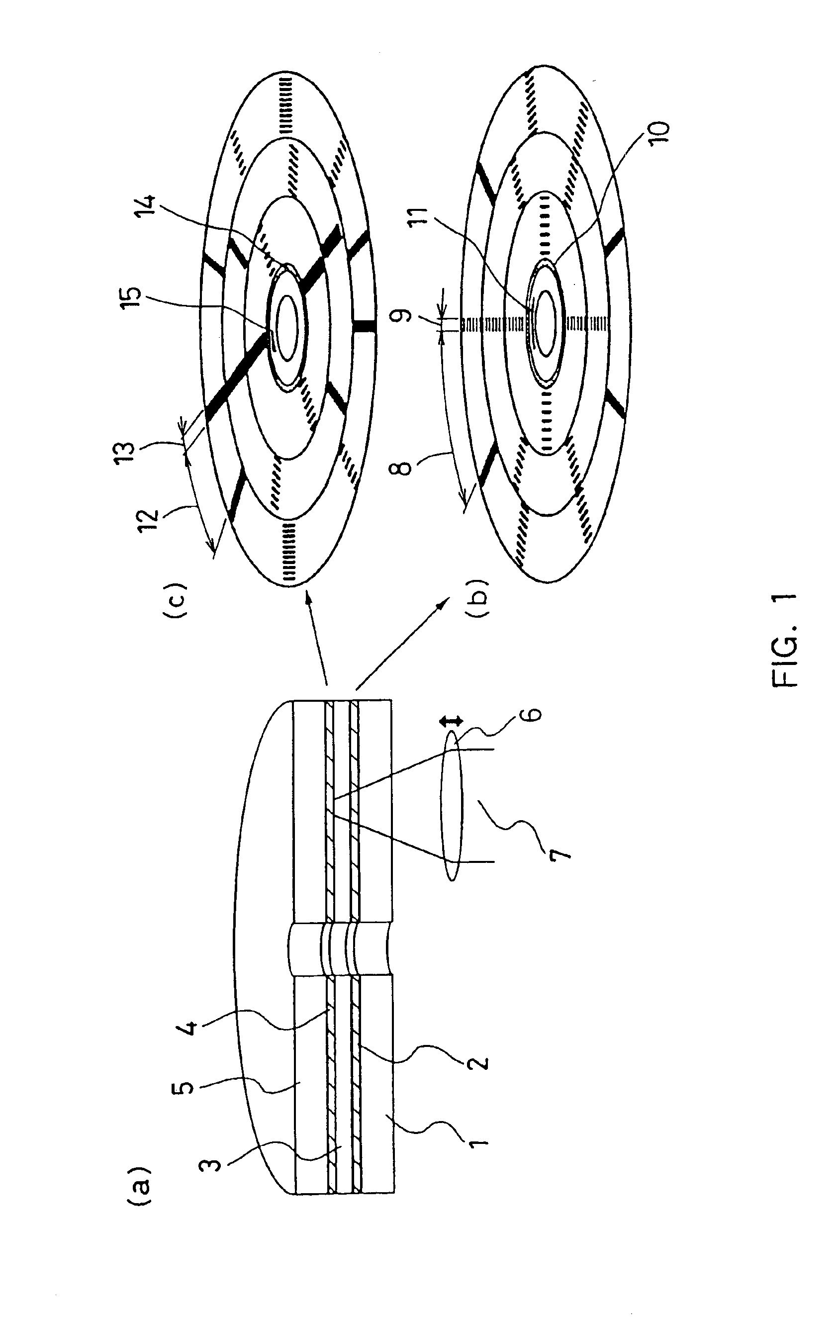
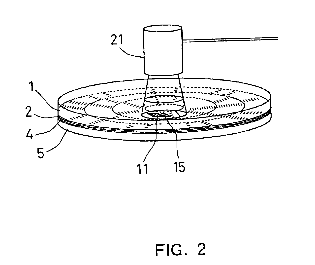
[0057]FIG. 1 shows a configuration of an optical information recording medium according to Embodiment 1 of the present invention. FIG. 1(a) is a cross-sectional view of the optical information recording medium that includes a first information layer 2, a separating layer 3, a second information layer 4, and a protective plate 5 in this order on a substrate 1. Information signals are recorded / reproduced on the first information layer 2 with a light beam 7 focused by an objective lens 6 from the side of the substrate 1, and the light beam through the first information layer 2 is used for recording / reproduction on the second information layer 4.

[0058]FIG. 1(b) shows a configuration of a recording area of the first information layer 2. The recording area has a sector structure including data portions 8 for recording information signals and sector address portions 9 for managing the location of data to be recorded. The recording medium of this embodiment employs the sector format referre...

embodiment 2

[0109]In Embodiment 1, the disk position identifiers are provided on each information layer in a recording medium to detect the amount of sector dislocation. On the other hand, a method for detecting the amount of sector dislocation of this embodiment does not require the disk position identifiers.

[0110]Hereinafter, the method will be described specifically with reference to FIG. 9. A signal is recorded on a recordable management area or the continuous tracks in a data area of a first information layer. In this case, at least one sector or more remains unrecorded in the circumferential direction.

[0111]FIG. 9(a) shows the first information layer, where data are recorded on the continuous tracks of a first sector (i.e., the portion indicated by reference numeral 92) in the data potions of the first information layer. In this drawing, the detailed illustration of a second information layer is omitted. It is preferable that the number of continuous tracks of the first information layer ...

embodiment 3

[0118]Each of the above embodiments relates to a method for suppressing the fluctuation in amplitude caused by the recorded state in the track direction or the fluctuation in recording power. This embodiment relates to a method for achieving stable recording / reproduction by further reducing the fluctuation factors resulting from the recorded state in the track direction of the information layer on the light incident side.

[0119]FIGS. 4, 6, and 8 show a change in the level of the reproduced signal from the second information layer 4, depending on whether the first information layer 2 is recorded or not. In each case, a change in the amount of light passing through the sector address portions in the track direction is compensated.

[0120]However, when a light beam is focused on the second information layer 4, the area of the first information layer 2, through which the light beam is transmitted, depends mainly on the thickness of a separating layer and the NA of an objective lens. Here, ...


PUM

PropertyMeasurementUnit
thicknessaaaaaaaaaa
diameteraaaaaaaaaa
transparentaaaaaaaaaa

Abstract

An optical information recording medium includes a substrate 1 and two information layers (2, 4) formed on the substrate. The information layer is formed of a thin film showing a change that can be detected optically by irradiation of a light beam 7. A separating layer 3 that is transparent to a wavelength of the light beam 7 is formed between the information layers 2 and 4. Each information layer (2, 4) includes a sector area having sector address portions (9, 13) and data areas (8, 12) for recording information signals, the sector address portion and the data area being divided in the circumferential direction, and a management area (10, 14) for recording identification information about the amount of dislocation between the sector address portions 9 and 14 in the circumferential direction. Thus, the identification information about the amount of dislocation can be recorded, so that demodulation errors during reproduction can be reduced by switching amplification gain or slice level during reproduction according to the identification information. Also, stable data recording can be achieved by switching recording power according to a gate signal.

Description

[0001]This application is a 371 of PCT / JP99 / 05771 filed Oct. 19, 1999.TECHNICAL FIELD[0002]The present invention relates to a recording medium having a multilayer structure in which optically recordable and reproducible information layers are laminated, and to a recording / reproducing method and apparatus for the same.BACKGROUND ART[0003]Conventionally, optical disks or optical cards are known as optical information recording media, on which information can be recorded or reproduced optically. These recording media use a semiconductor laser as a light source, and a great deal of information can be recorded or reproduced by irradiation of light that is finely focused through a lens.[0004]At present, there is much research on the above recording media to increase their recording capacities. For example, a recording medium having a multilayer structure whose recording capacity is doubled by laminating information layers to record / reproduce information signals has been proposed (U.S. Pat...

Claims


Application Information

Patent Timeline
Patent Type & Authority Patents(United States)
IPC IPC(8): G11B7/125G11B20/12G11B7/0045G11B7/005G11B7/007G11B7/00G11B7/26G11B7/24
CPCG11B7/0045G11B7/007G11B7/00745G11B7/126G11B20/1217G11B7/005G11B2220/2562G11B7/24G11B7/26G11B2007/0013G11B2020/1227G11B2020/1232G11B2020/1267G11B2020/1275G11B2020/1278G11B2020/1288G11B2020/1298G11B2220/235G11B2220/237G11B2220/2537G11B2220/2545
Inventor NISHIUCHI, KENICHINAGATA, KEN'ICHI
Owner PANASONIC CORP
Why Eureka
Try Eureka