Apparatus for counting rotation frequency of numeral wheel of meter for remote meter reading system

Inactive Publication Date: 2005-05-17
CHOIS T&M
View PDF6 Cites 14 Cited by
  • Summary
  • Abstract
  • Description
  • Claims
  • Application Information

AI Technical Summary

Benefits of technology

[0013]To solve the above problems, it is an object of the present invention to provide an apparatus for counting the rotation frequency of a numeral wheel of a me

Problems solved by technology

A manual meter reading method, by which in order to read a meter for the amount of the supply used, a meter-reading person visits each consumer's house and reads a meter, needs a lot of time and efforts and also causes much inconvenience.
However, since this needs to replace existing mechanical type meters, the expense is high, and the economic efficiency is low.
Accordingly, it is difficult to practically apply this to ordinary household use.
However, the meter also has the problem that an existing mechanical meter cannot be used as is, and it is highly probable that a metering error by a magnet occurs.
In this case, it is very difficult to distinguish the reflection section from the non-reflection section, which may result in a great deal of error in automatic meter reading.
However, this method increases power consumption and reduces a replacement cycle for battery which is

Method used


Image

  • Apparatus for counting rotation frequency of numeral wheel of meter for remote meter reading system
  • Apparatus for counting rotation frequency of numeral wheel of meter for remote meter reading system
  • Apparatus for counting rotation frequency of numeral wheel of meter for remote meter reading system

Examples


Example

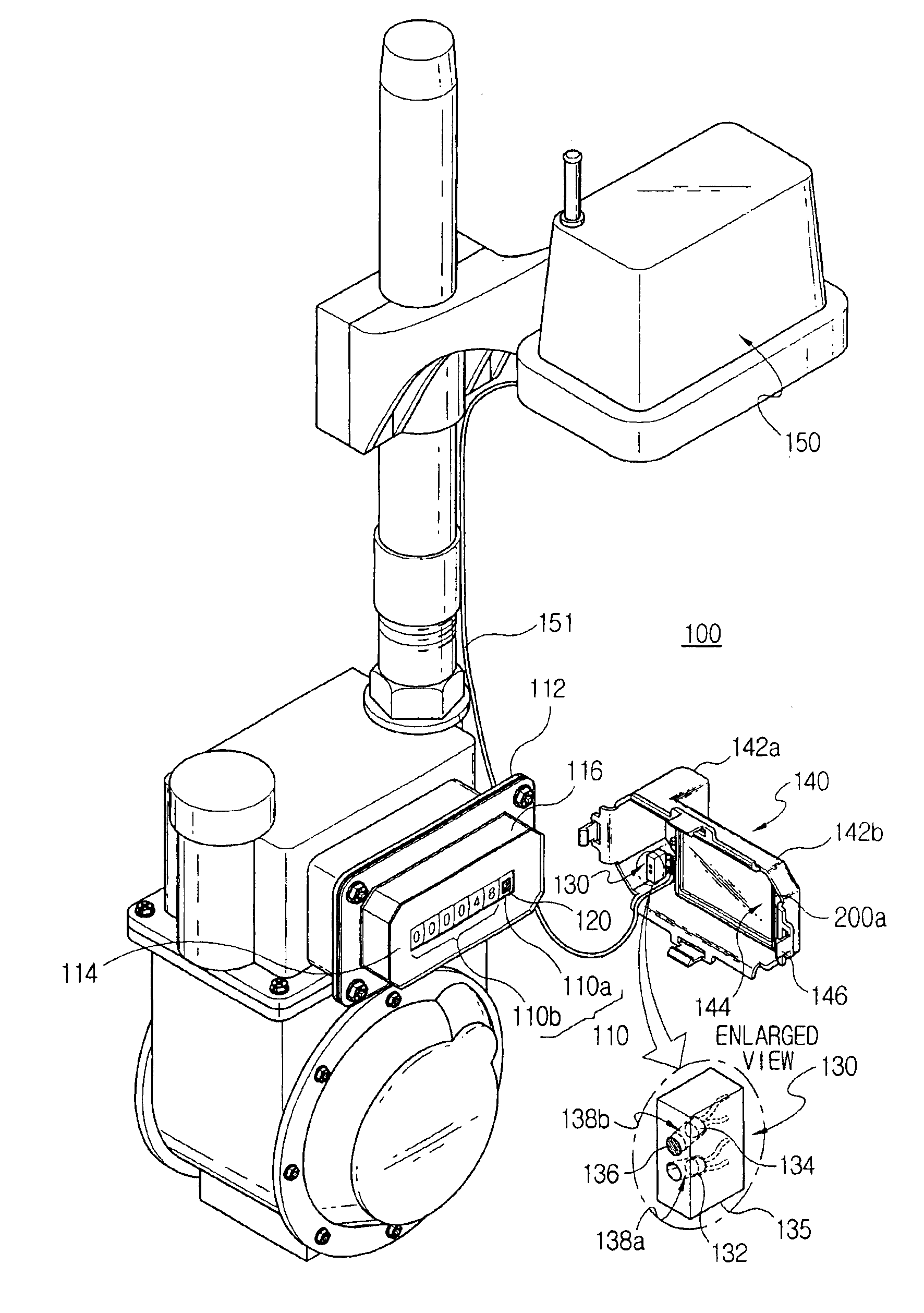
[0027]First, a numeral wheel counter 110 of an existing mechanical-type meter to which the apparatus according to the present invention is applied will now be explained briefly. A numeral wheel counter of a meter indicating the amount of supply usage is formed by closely arranging a plurality of numeral wheels to show roughly 4˜5 integer digits and 1˜3 decimal digits. Each numeral wheel has a drum shape and numbers from 0 to 9 expressed on the outer surface of it. If a supply such as gas, water, or electricity is used, the lowest numeral wheel of the numeral wheel counter 110 in the meter rotates at the fastest speed in proportion to the amount of the supply usage, and the ratio of the rotation speed of a first numeral wheel to that of a second numeral wheel which is one-digit higher than the first numeral wheel is 10 to 1.

[0028]FIGS. 3a and 3b are diagrams of the structure of an apparatus for counting the rotation frequency of a numeral wheel of a meter according to a preferred emb...


PUM


Abstract

Disclosed is an apparatus for counting the rotation frequency of a numeral wheel of a meter to be used for a remote metering system. A light reflection tape is coated on one of low placed numeral wheels. A light sensor unit has an opaque case formed with first and second holes in which an infrared ray emitter and an infrared ray sensor are located, respectively. The light sensor unit is fixedly mounted on the ceiling of a rectangular shaped housing which is detachably coupled with a meter to cover the front of the meter. A portion of the housing over numeral wheels and a front plate of the meter is transparent. The transparent portion of the housing has an infrared ray rejection function to prevent infrared rays from entering into the housing. In place of employing such housing, a light shield may be used to shield a space between the light sensor unit and the light reflection tape coated numeral wheel from outer light. A microprocessor counts the rotation frequency of the light reflection tape coated numeral wheel by counting the number of output pulses from the infrared ray sensor to measure an amount of a supply, for example, gas used, A power supply portion using batteries supplies the light sensor unit and the microprocessor with necessary power. Particularly, for the minimum consumption of the battery power, an input signal for the infrared ray emitter is made in a pulse form signal of which duty ratio is under 1/100.

Description

BACKGROUND OF THE INVENTION[0001]1. Field of the Invention[0002]The present invention relates to a remote meter reading system for a meter, and more particularly, to an apparatus for counting the rotation frequency of a numeral wheel of a meter which counts the rotation times of the numeral wheel of a predetermined digit in existing meters by a light sensing method, so that the used amount of a supply such as gas can be monitored from a remote place.[0003]2. Description of the Prior Art[0004]The amount of usage of supplies, such as electricity, gas, or water, is metered when the supplies pass through a meter. The amount of usage is expressed by a number value of a numeral wheel counter disposed on the front side of a meter. The charge for supply usage is determined with respect to the amount of usage. A manual meter reading method, by which in order to read a meter for the amount of the supply used, a meter-reading person visits each consumer's house and reads a meter, needs a lot o...

Claims


Application Information

Patent Timeline
IPC IPC(8): G01F15/06G01D5/26G01D5/28
CPCG01F15/061G01D5/28G01D5/26G01D7/002
Inventor KIM, JOO YOUNG
Owner CHOIS T&M
Why Eureka
Try Eureka