Coriolis mass flowmeter

Inactive Publication Date: 2005-05-24
OVAL CORP
View PDF20 Cites 39 Cited by
  • Summary
  • Abstract
  • Description
  • Claims
  • Application Information

AI Technical Summary

Benefits of technology

[0023]This invention can provide a pressure-resistant container that is reliable even in case of damage to a tube by imparting a very high pressure resistance even with thin walls by integrally fitting an inverted U-shaped case 31 to the meter body 30 of a U-shaped cross section and has a circular-arc outer periphery, with rounded corners.
[0024]This invention can prevent inertial moment caused by vibration inertial force from being generated by disposing a drive unit 15 and a pair of vibration sensors 16, 17 between the two flow tubes and aligning them with the central axes of the tubes.
[0025]This invention can perfectly maintain the symmetry of vibration beams without being affected by the secondary vibration mode, and isolate external vibration almost completely by disposing a pair of vibration sensors 16, 17 at the nodes of the secondary vibration mode at the proximal parts at the inlet and outlet sides.
[0026]This invention can obtain very stable vibration and very high accuracy without being affected by external vibration by providing the wiring to the drive unit 15 and a pair of the vibration sensors 16, 17 using flexible printed circuit boards 12, 13 bent symmetrically from both sides of the flow tubes, and making additional mass and additional stress symmetrical.
[0027]A drive unit coil 3 is installed on a flow tube 1, and a drive unit magnet 6 is the other flow tube 2, whereas vibration sensor magnets 7 and 8 are installed on a flow tube 1 on which the drive unit coil 3 is installed, and v

Problems solved by technology

Despite its simple, compact and sturdy construction, the straight-tube Coriolis mass flow meter cannot accomplish high detection sensitivity.
However, this conventional type of Coriolis mass flow meter using two parallel curved flow tubes has not been perfect in isolating external vibration.
In the conventional type of Coriolis mass flow meter, however, the second fulcrum has not been perfectly isolated from vibration transmitted from the outside.
As a result, external vibration transmitted from the meter structures, casing, etc. has had adverse effects on the performance of the Coriolis mass flow meter.
Furthermore, since this t

Method used


Image

  • Coriolis mass flowmeter
  • Coriolis mass flowmeter
  • Coriolis mass flowmeter

Examples


Embodiment Construction

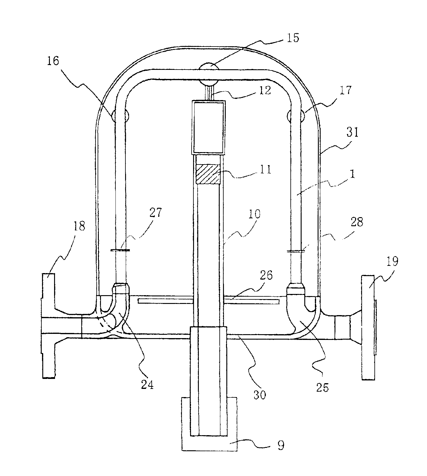
[0040]Although this invention can be applied equally to Coriolis mass flow meters of all types using two parallel flow tubes, a Coriolis mass flow meter of a gate type will be specifically described in the following as a typical example of the two parallel curved tube type.

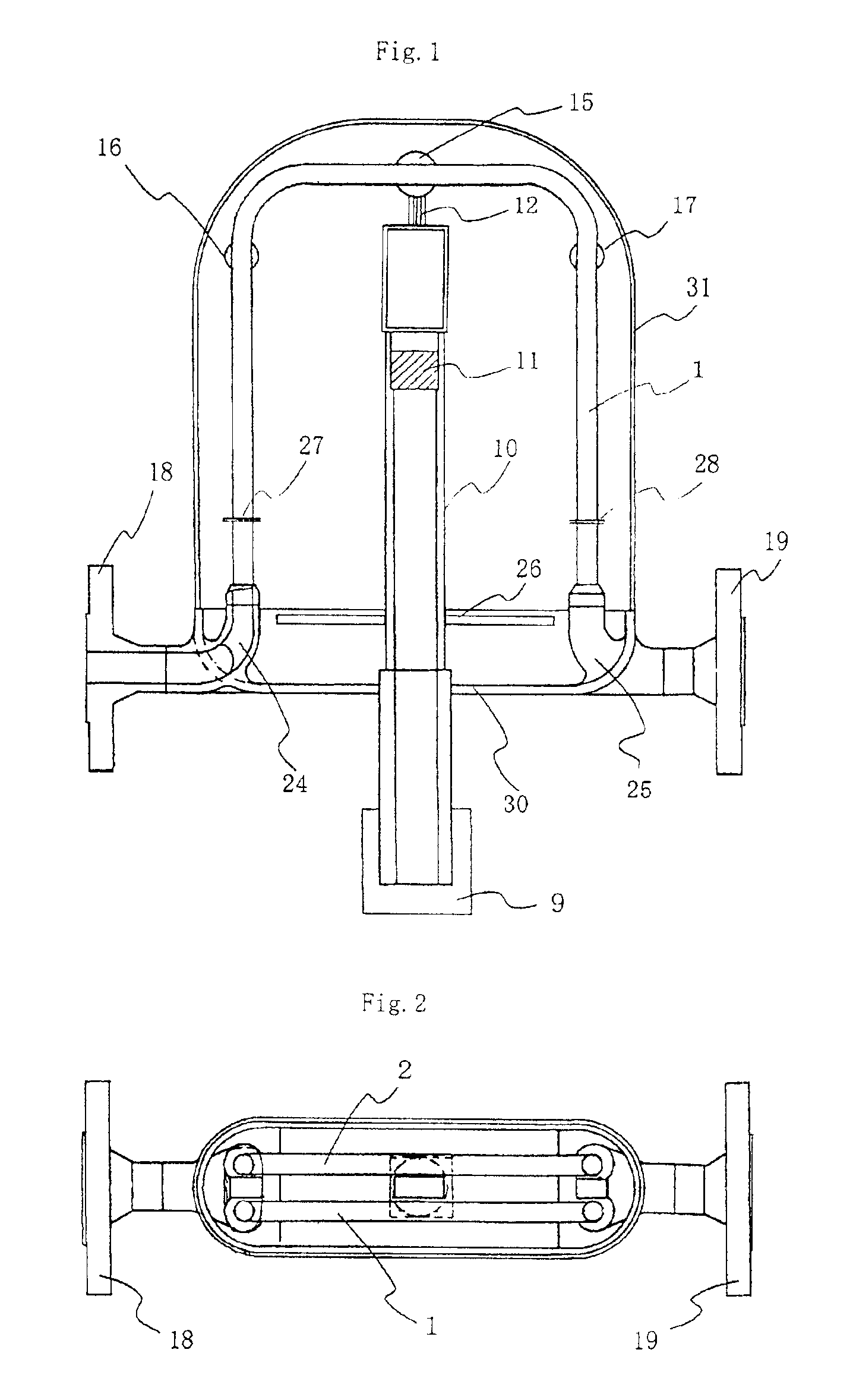
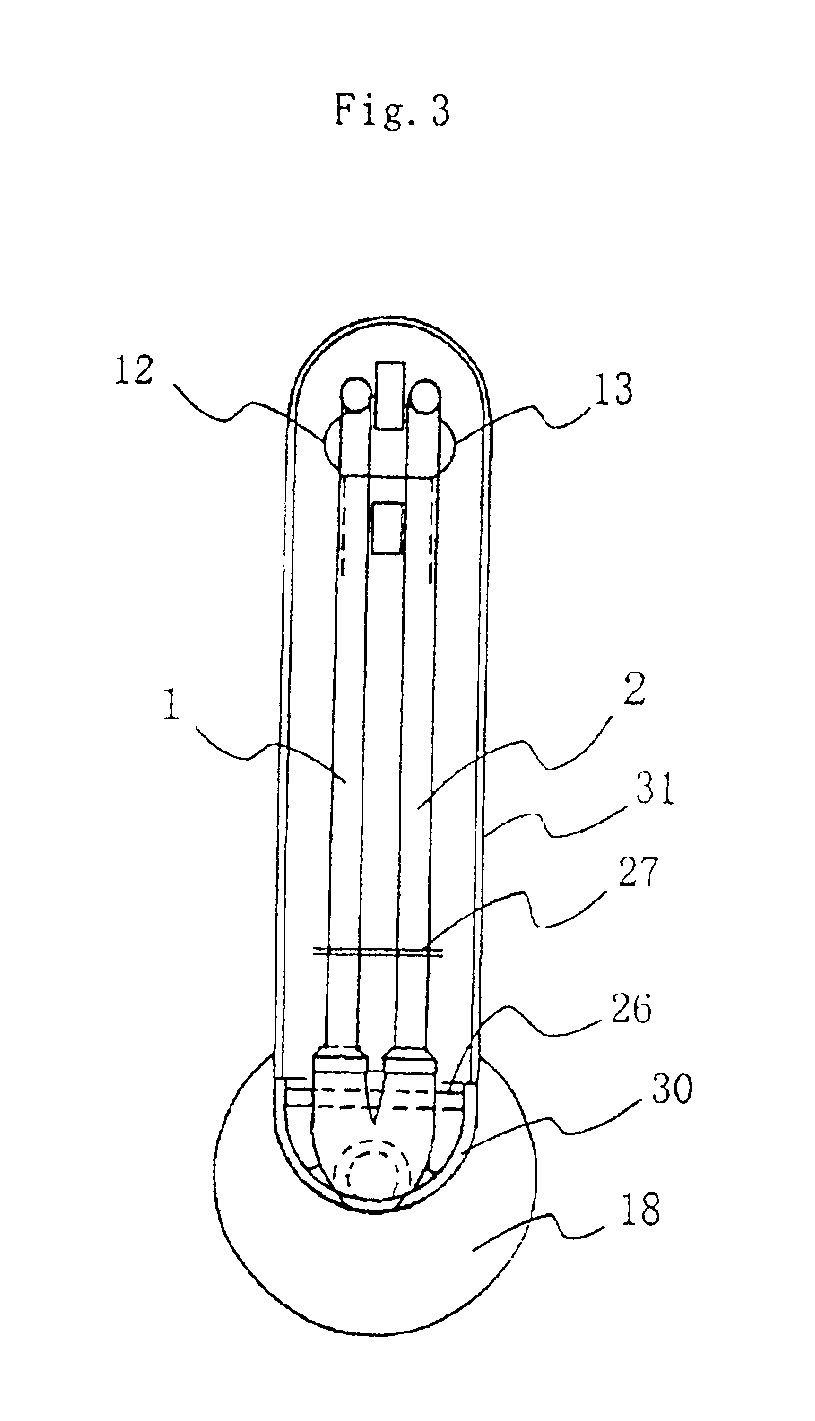
[0041]FIGS. 1 through 3 are diagrams illustrating a first example of Coriolis mass flow meter to which this invention is applied, where flow tubes comprising of two parallel curved tubes are installed on a vertical plane. FIG. 1 is a partially cross-sectional front view of a Coriolis mass flow meter. FIG. 2 is a partially cross-sectional top view of the Coriolis mass flow meter installed on a vertical plane (shown in FIG. 1). FIG. 3 is a cross-sectional side view of the Coriolis mass flow meter shown in FIG. 1.

[0042]Flow tubes 1 and 2 of the Coriolis mass flow meter shown in the figures are two inverted U-shaped tubes formed into substantially the same shape, with both ends thereof connected to manifolds 24 and 25...


PUM


Abstract

The Coriolis mass flow meter of this invention comprises two parallel curved flow tubes 1 and 2, a drive unit 15, and a pair of vibration sensors 16 and 17. An inlet-side manifold 24 dividing the flow of a fluid being measured into the two flow tubes 1 and 2 from the inlet thereof, and an outlet-side manifold 25 joining the fluid flows flowing in the two flow tubes 1 and 2 to discharge from the fluid outlet thereof are mechanically connected to a meter body 30 only at the inlet side of the inlet-side manifold 24 and at the outlet side of the outlet-side manifold 25, respectively. With this arrangement, the effects of vibration transmitted from the meter body 30 and all structures connected thereto can be reduced at the joint parts between the inlet-side and outlet-side manifolds 24 and 25 that serve as vibration fulcrums.

Description


Claims


Application Information

Patent Timeline
Owner OVAL CORP
Why Eureka
Try Eureka