Seat structure

Inactive Publication Date: 2005-05-24
APRICA CHILDRENS PROD
View PDF16 Cites 19 Cited by
  • Summary
  • Abstract
  • Description
  • Claims
  • Application Information

AI Technical Summary

Benefits of technology

[0014]An object of the present invention is to provide a seat stru

Problems solved by technology

Any adopted structure cannot avoid the formation of concave and convex in the coupling portion between the seat portion and the backrest portion.
When the baby's pain sensation is stimulated by the load locally acting upon the baby's buttocks, the baby feels uncomfortable, resul

Method used


Image

  • Seat structure
  • Seat structure
  • Seat structure

Examples


Embodiment Construction

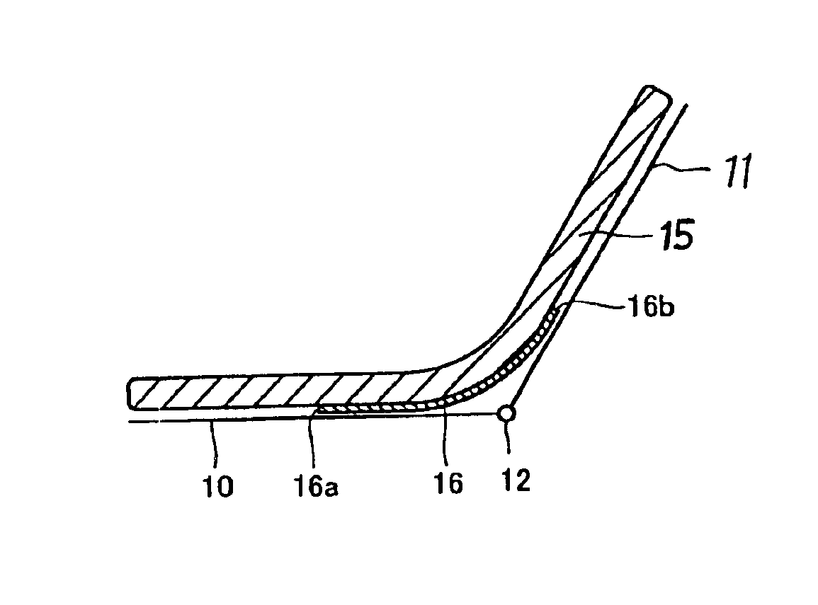
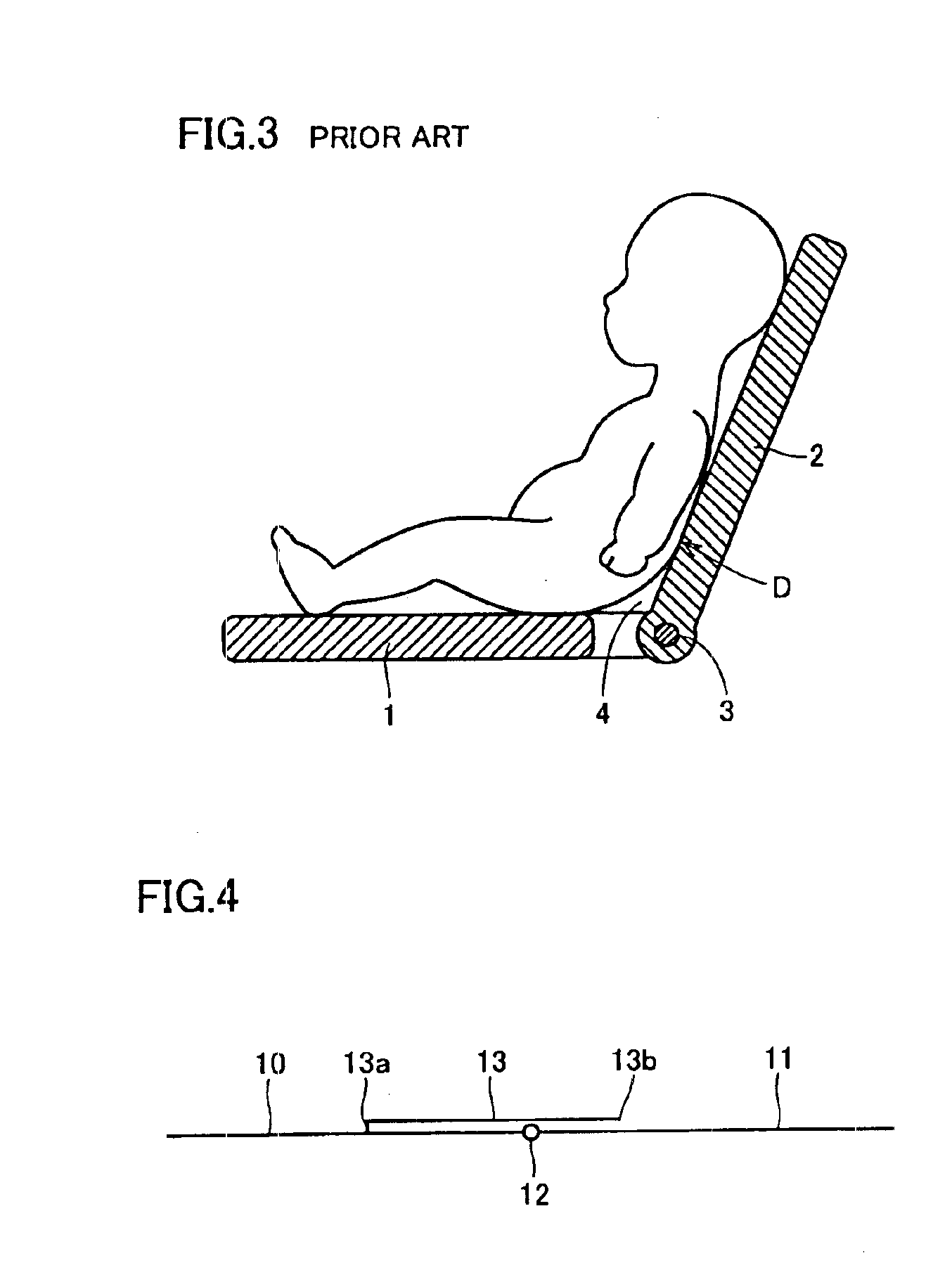
[0033]FIG. 4 schematically shows a seat structure in accordance with an embodiment of the present invention. The seat structure shown is a seat assembly for nursing equipment such as baby carriages, baby racks and child seats, including a seat plate 10 formed of a rigid material and a backrest plate 11 pivotably coupled to seat plate 10 by means of a shaft 12. The seat assembly is formed such that it can be switched between the form of a chair and the form of a bed by adjusting an inclination angle of backrest plate 11. FIG. 4 shows the seat in the form of a bed.

[0034]As shown, a bridging member 13 is arranged on a flexion portion (coupling portion) between seat plate 10 and backrest plate 11. Bridging member 13 is preferably a member shaped like a thin flat plate exerting an elastic force against a bending force and has its one end 13a coupled to seat plate 10 by an adhesive or the like. The other end 13b of bridging member 13 is a free end and may slide on backrest plate 11 in acc...


PUM


Abstract

A seat structure includes a seat plate, a backrest plate adjustable in inclination angle, and a bridging member covering up a flexion portion between the seat plate and the backrest plate for bridging the seat plate and the backrest plate smoothly. The bridging member is a member shaped like a thin flat plate having a flexural elasticity and stably supports a baby's buttocks while dispersing a body pressure with its entire surface. This structure can provide such a seat structure that can prevent local loads from acting on the buttocks both in the form of a bed and in the form of a chair.

Description

BACKGROUND OF THE INVENTION[0001]1. Field of the Invention[0002]The present invention relates to a seat structure including a seat portion and a backrest portion adjustable in inclination angle, and more particularly to a seat structure suitable for nursing equipment.[0003]2. Description of the Background Art[0004]In nursing equipment such as a baby carriage, a baby rack and a child seat, an inclination angle of a backrest portion of a seat is usually adjustable. In the nursing equipment receiving a baby shortly after birth, the backrest portion is inclined backward to an approximately horizontal state in order to realize a bed state. Nursing equipment that can be switched between the form of a bed and the form of a chair in accordance with the developmental stages of infants is commercially available.[0005]FIG. 1 is a view showing a partial seat of nursing equipment in the form of a bed as seen from above. The seat includes a seat portion 1 and a backrest portion 2 adjustable in in...

Claims


Application Information

Patent Timeline
IPC IPC(8): A47D1/00A47C3/12A47C3/00A47C4/28A47C7/00A47C13/00A47D1/02
CPCA47D1/002A47D11/005
Inventor KASSAI, KENZOUONISHI, ICHIRO
Owner APRICA CHILDRENS PROD
Why Eureka
Try Eureka