Granular product blending and cooling rotary drum

a technology of granular products and rotary drums, which is applied in the direction of drying machines, transportation and packaging, light and heating equipment, etc., can solve the problems of insufficient heat removal of hot granular products by exposure to airflow only at the discharge end, and achieve the effect of efficient blending, cooling and screening

Inactive Publication Date: 2005-05-24
DIDION TECHNOLOGIES LLC
View PDF17 Cites 14 Cited by
  • Summary
  • Abstract
  • Description
  • Claims
  • Application Information

AI Technical Summary

Benefits of technology

[0008]Briefly stated, the invention sets forth a rotary drum configuration for the efficient blending, cooling, and screening of granular products. The rotary drum is of the type that is an elongated structure, generally having an outer cylindrical shell, an intake end, and a discharge end. The rotary drum is normally rotated at a predetermined speed by means of a conventional drive package. Disposed on an inner surface of the cylindrical shell are a plurality of compound helical flights and scoops, configured to blend granular product as it cascades from the intake end to the discharge end of the rotary drum. A coaxially disposed cylindrical air passage adjacent the discharge end of the rotary drum directs a counter flow of cooling air through the rotary drum towards the intake end, cooling the cascading granular product as it approaches the discharge end. A plurality of discharge ports and grading screens in the surface of the outer cylindrical shell adjacent the discharge end provide a entrance for a second counter flow of cooling air while simultaneously providing passage for the granular product to drop downwards towards a outer coaxial discharge passage. A series of external helical flights on the outer surface of the cylindrical shell urge granular product in the outer coaxial discharge passage out the discharge end of the rotary drum. The upper section of the discharge end contains an opening therethrough, and mounted in proximity with the opening, or in communication through duct work with the opening, is a vacuum pump which is designed to provide a reduced pressure for attracting air, particularly that air in which the dust and sand fines from the granular product are entrained, so as to achieve their removal.

Problems solved by technology

However, it has been found that the removal of heat from hot granular products by exposure to an airflow only at the discharge end is insufficient to reduce the temperature of the granular products to near ambient temperatures.

Method used


Image

  • Granular product blending and cooling rotary drum
  • Granular product blending and cooling rotary drum
  • Granular product blending and cooling rotary drum

Examples


Embodiment Construction

[0020]The following detailed description illustrates the invention by way of example and not by way of limitation. The description clearly enables one skilled in the art to make and use the invention, describes several embodiments, adaptations, variations, alternatives, and uses of the invention, including what is presently believed to be the best mode of carrying out the invention.

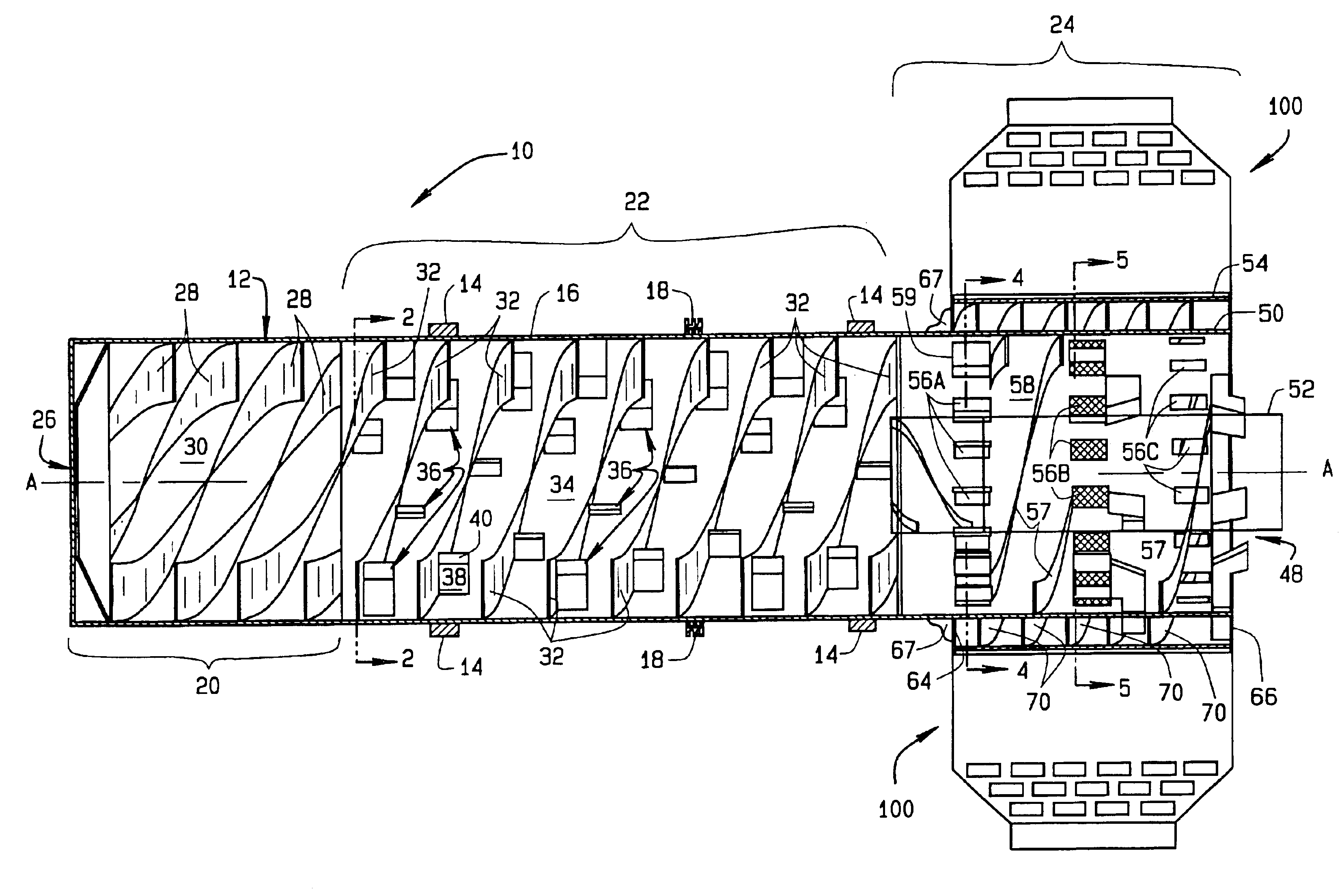
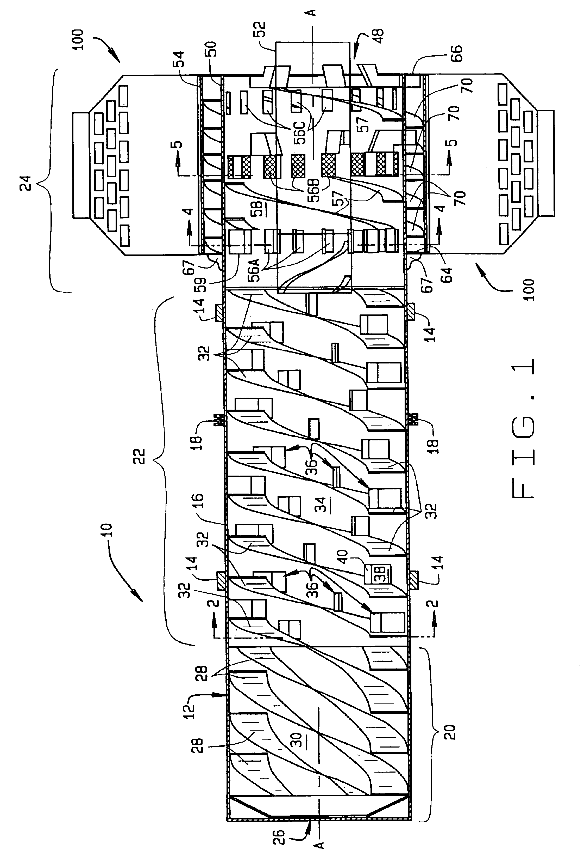
[0021]Turning to FIG. 1, a rotary drum of the present invention for effecting the blending and cooling of granular product is shown generally at 10. The rotary media drum 10 comprises a cylindrical drum body 12, which is includes a plurality of spaced circumferential drum assembly tires 14 disposed on an external surface 16. The circumferential drum assembly tires support the rotary drum 10 on a conventional base (not shown). Correspondingly, a circumferential sprocket 18 on the external surface 16 engages a conventional drive mechanism (not shown) in the conventional base to drive the rotary drum 10 at a...


PUM

PropertyMeasurementUnit
speedaaaaaaaaaa
temperatureaaaaaaaaaa
temperaturesaaaaaaaaaa

Abstract

A rotary drum configuration for the efficient blending, cooling, and screening of granular products having an outer cylindrical shell, an intake end, and a discharge end. The rotary drum is normally rotated at a predetermined speed by means of a conventional drive package. Disposed on an inner surface of the cylindrical shell are a plurality of compound helical flights and scoops, configured to blend granular product as it cascades from the intake end to the discharge end of the rotary drum. A coaxially disposed cylindrical air passage adjacent the discharge end of the rotary drum directs a counter flow of cooling air through the rotary drum towards the intake end, cooling the cascading granular product as it approaches the discharge end, and plurality of discharge ports and grading screens in the surface of the outer cylindrical shell adjacent the discharge end provide a entrance for a second counter flow of cooling air while simultaneously providing passage for the granular product to drop downwards towards a outer coaxial discharge passage.

Description

CROSS-REFERENCE TO RELATED APPLICATIONS[0001]Not Applicable.STATEMENT REGARDING FEDERALLY SPONSORED RESEARCH[0002]Not Applicable.BACKGROUND OF THE INVENTION[0003]The present invention relates generally to a rotary drum as used in the granular product drying field, and having a major application for the treatment of heated and moist granular products such as mold sands, grains, and fertilizers as to achieve the reclaiming, cooling, and blending of the mold granular product and in particular, to a dust collection hood and discharge chute configured to convey multiple air streams through the rotary drum for the cooling of the granular product.[0004]There are a variety of prior patents that have been obtained upon various styles of rotary drums for use in the metal casting industry. For example, one of the early embodiments is that which is shown in U.S. Pat. No. 3,998,262 to Charles J. Didion, showing a casting shakeout unit and method of operation. Essentially, such a drum is arranged...

Claims


Application Information

Patent Timeline
Patent Type & Authority Patents(United States)
IPC IPC(8): B01F15/00B01F15/06B01F9/06B01F9/00F26B11/02F26B11/04F26B11/00B01F3/00B01F3/18B01F29/63
CPCB01F9/06F26B11/0477F26B11/026B01F15/063B01F3/18B01F2015/061B01F23/60B01F29/63B01F35/91B01F2035/98
Inventor DIDION, CHARLES J.
Owner DIDION TECHNOLOGIES LLC
Why Eureka
Try Eureka